


IRF3205 55V 110A MOSFET for Solar Systems: Efficiency, Design & Benefits
The IRF3205 is a 55V, 110A N-channel MOSFET, widely used in solar power systems for its low RDS(on), high current capacity, and excellent switching performance. Its efficiency in handling high-power applications makes…

I have replaced more burnt MOSFETs in solar charge controllers than I can count. Most of them died for one of two reasons: the part was a cheap fake, or the design pushed a good part past its real limits. Both problems are avoidable, and that is why I wrote this guide.
I work with these components every day at SunTech Mall. I test them, I sell them, and I hear the repair stories when things go wrong. So I know the IRF3205 from the bench, not just the datasheet.
If you are building or repairing a solar charge controller, an inverter, or a DC-DC converter, your fear is simple: pick the wrong MOSFET and your board smokes on the first hot afternoon. Pick a fake and it dies even sooner.
By the end of this guide, you will know the real IRF3205 specifications, how much power it actually wastes as heat, exactly where it fits in a solar system, and how to wire it so it survives years of service. No guesswork, no marketing fluff.
Let us start with the numbers that matter — straight from the datasheet.
Quick honesty note: this is not a paid review. I stock and test the IRF3205 at SunTech Mall, and I want you to buy the right part, even if the right part turns out to be something else. That is why this guide ends with an honest section on when you should NOT use the IRF3205.
What You Will Learn in This Guide
- The real IRF3205 specs, read the way a repair tech reads them
- How much power it wastes as heat at real solar currents
- Where it works hardest in your solar system
- How to wire and cool it so it never burns
- When to choose a different MOSFET instead
The Real IRF3205 Specs (Read Like a Repair Tech)
The first time I tested an IRF3205 on my bench, I understood why repair shops across Pakistan keep boxes of them. It is a classic HEXFET N-channel power MOSFET, and its numbers are honest workhorse numbers.
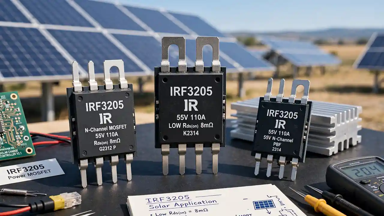
Here are the datasheet values that actually decide your design:
- Drain-to-source voltage (Vds): 55V — your hard ceiling, never cross it
- Continuous drain current (Id): 110A at 25°C case temperature, dropping to 75A at 100°C
- On-resistance (Rds(on)): 8 mΩ maximum at 10V gate drive
- Gate-to-source voltage (Vgs): ±20V maximum rating
- Gate threshold (Vgs(th)): 2.0 to 4.0V — it starts turning on here, but this is NOT full conduction
- Total gate charge (Qg): 146 nC
- Power dissipation (Pd): 200W with ideal cooling
- Operating temperature: -55°C to +150°C junction
- Package: TO-220AB, the familiar three-pin tab package
The single most important number on that list is the Rds(on) of 8 mΩ. That tiny resistance is the reason this MOSFET runs solar systems efficiently, and the next section shows you the math.
One caution I always give: that 110A rating assumes a 25°C case, which you will never have in a real Pakistani summer. At a 100°C case temperature the rating falls to 75A. Design for the hot number, not the pretty one. If you want a deeper walkthrough of picking parts the right way, read our power MOSFET selection guide.
Note: Some older write-ups list the maximum junction temperature as 175°C. The manufacturer datasheet specifies -55°C to +150°C, and that is the number used in this guide. Always trust the datasheet over old blog posts — including this site’s older ones.
How Much Power It Actually Wastes (The Efficiency Math)
Here is the moment most hobbyists skip, and it is the moment that kills boards. A MOSFET wastes power mainly through its on-resistance, and the formula is simple: power loss = current² × Rds(on).
Run the numbers with me at real solar currents:
- At 20A: 20 × 20 × 0.008 = 3.2W of heat — barely warm with a small heatsink
- At 30A: 30 × 30 × 0.008 = 7.2W — needs a proper heatsink, still comfortable
- At 50A: 50 × 50 × 0.008 = 20W — serious cooling territory, think fan or a big finned sink
See how fast it climbs? Current squared is brutal. This is why the low 8 mΩ figure matters so much — a MOSFET with 25 mΩ would waste three times the heat at the same current, and your solar harvest would drop by the same amount.
Switching losses are the second half of the story. The IRF3205 carries a total gate charge of 146 nC, which is moderate. In PWM charge controllers, it switches fast enough to keep transition losses small. Your gate driver needs to deliver that charge quickly, which brings us to wiring.
Real talk from the repair bench: most burnt MOSFETs in solar inverters did not die because the part was weak. They died because the design ignored one of these heat numbers. Do the math before you solder.
Where the IRF3205 Works Hardest in Your Solar System
Last month a customer brought in a PWM charge controller with two dead MOSFETs and asked why this exact part sits in so many solar products. Four jobs, as it turns out.
Solar Charge Controllers
This is the IRF3205’s home turf. In PWM charge controllers, it switches the panel-to-battery path thousands of times per second. Its low on-resistance keeps charging losses tiny, which means more of your panel’s power actually reaches the battery. For 12V and 24V systems, the 55V rating gives comfortable headroom.
Solar Inverters
In inverters, banks of IRF3205s handle the heavy DC switching before the output stage. The 110A current rating (75A hot) lets a handful of devices move serious power. Parallel them, cool them, and they will run a household inverter for years.
DC-DC Converters
Step-up and step-down converters in solar setups lean on the IRF3205’s fast switching and low conduction loss. Every watt you save in conversion is a watt your panels do not have to produce twice.
Battery Management and Load Switching
The IRF3205 also shines as a high-current switch — battery disconnect circuits, load control, and protection stages. When the gate is driven fully on, that 8 mΩ resistance is nearly invisible to your circuit.
If you are still deciding between MOSFET types for a switching stage, our MOSFET vs IGBT comparison will help you choose with confidence.
Bonus Tip: When replacing a burnt MOSFET in a charge controller or inverter, replace the whole parallel set, not just the dead one. The survivors have lived through the same abuse and usually fail weeks later. A full fresh set costs little and saves a second repair trip.
How to Wire It So It Never Burns
I once watched a neat, well-built inverter die in under a minute because the builder drove the gates with 5V logic straight from a microcontroller. The gates starved, resistance stayed high, and heat did the rest. Wiring matters as much as the part.
Drive the Gate With 10 to 15 Volts
The threshold is 2 to 4V, but threshold only starts the turn-on. For the full rated 8 mΩ, drive the gate with 10 to 15 volts. Use a proper gate driver IC or a driver stage — never raw logic pins for high-current switching. A weak gate drive is the number one cause of mysterious MOSFET heating.
Cool It Like You Mean It
The 200W dissipation rating assumes a perfect, infinite heatsink — which does not exist. In practice, bolt every IRF3205 to a real finned heatsink with thermal paste, and add a fan once you cross roughly 30 to 40A per device. In Pakistani summer heat, generous cooling is not optional.
Paralleling for Bigger Loads
Need more than one device can safely carry? You can parallel IRF3205s. Give each MOSFET its own small gate resistor (around 10 ohms is a common choice) so they share the switching load evenly, keep the layout symmetric, and mount them on the same heatsink so they track each other thermally.
Tame the Spikes With Snubbers
Fast switching creates voltage spikes from stray inductance. A simple RC snubber across the device absorbs those spikes and protects the 55V rating from being exceeded for even a microsecond. It is cheap insurance, and commercial designs almost always include it.
Note: Never exceed the ±20V gate rating, not even briefly. Gate oxide damage is silent — the MOSFET may test fine on a meter and then fail under load days later. If your driver supply can spike, clamp it.
When to Pick a Different MOSFET Instead
Honesty time, as promised. The IRF3205 is excellent, but it is not universal. Here is when I steer customers toward something else.
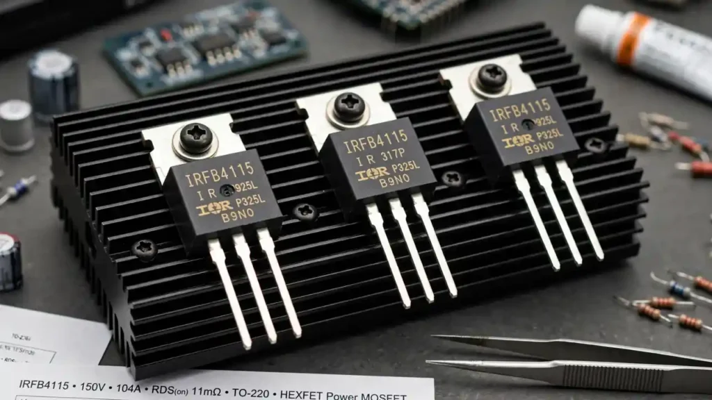
If your bus voltage runs above 55V — for example a 48V system with spikes, or a high-voltage string — the IRF3205 has no safety margin left. Step up to a higher-voltage device like the IRFB4115 (150V, 104A), which handles the same current class with far more voltage headroom.
If you need even lower conduction loss or higher current in a TO-220 package, look at options like the NCEP85T16 (85V, 160A). And for very high power stages, TO-247 parts such as the IRFP4668 (200V, 130A) give you a bigger package with better thermal paths.
Also, if your design switches above roughly 100 kHz, the 146 nC gate charge starts costing you real switching loss — a lower-charge modern MOSFET may serve you better. Browse the full MOSFET category at SunTech Mall to compare options side by side, and check current prices on SunTech Mall before you decide.
IRF3205 Frequently Asked Questions
Is the IRF3205 good for a 12V solar charge controller?
Yes, it is one of the most common choices. The 55V rating gives wide headroom over 12V panel voltages, the 8 mΩ resistance keeps charging losses low, and the TO-220 package is easy to heatsink. Just drive the gate with 10 to 15V and cool it properly.
Can I use the IRF3205 in a 24V solar inverter?
Yes, with proper design. A 24V nominal system stays well under the 55V ceiling, but allow margin for switching spikes and use snubbers. For high-power 24V inverters, parallel several devices on a shared heatsink rather than pushing one device near its limit.
How many IRF3205 MOSFETs can I connect in parallel?
There is no hard datasheet limit — commercial designs parallel four, six, or more. The practical rules: give each device its own gate resistor, keep wiring symmetric, and mount them on one shared heatsink so temperatures track together. Test current sharing under real load.
Does the IRF3205 need a heatsink?
At anything above a few amps, yes. Even 20A produces over 3W of heat per device, and it climbs with the square of current. A finned heatsink with thermal paste is the minimum for solar applications; add a fan for sustained currents above roughly 30 to 40A per device.
What gate voltage does the IRF3205 need?
Drive it with 10 to 15V for full conduction and the rated 8 mΩ resistance. The 2 to 4V threshold only begins turn-on — running a high-current load at threshold voltage will overheat the device fast. Never exceed the ±20V gate maximum.
What is the difference between IRF3205 and IRF3205PBF?
Electrically they are the same part. The PBF suffix marks the lead-free (Pb-free) version. For new builds, the lead-free variant is the standard choice; for repairs, either works identically in circuit.
How do I spot a fake IRF3205?
Common red flags: unusually low price, blurry or inconsistent laser marking, wrong package dimensions, and a device that runs hot at currents a genuine part handles easily. Buy from established suppliers who test their stock, and check current prices on SunTech Mall to calibrate what genuine parts cost.
Where can I buy a genuine IRF3205 in Pakistan?
You can order the IRF3205 N-channel power MOSFET from SunTech Mall — we stock genuine parts, test what we sell, and ship across Pakistan. For bulk repair-shop quantities, email info@suntechmall.com or WhatsApp +92 306 2244820.
Final Thoughts
The IRF3205 earned its reputation the hard way — inside millions of charge controllers, inverters, and converters that just keep working. But for 12V and 24V solar systems, its mix of 110A current handling, 8 mΩ resistance, and honest TO-220 ruggedness is still hard to beat in 2026.
If you read this whole guide, congratulations — you now know more about this part than most people who solder it. You know the real specs, you can calculate the heat before it surprises you, and you know exactly when to choose something else. That knowledge is what separates a board that lasts from a board that burns.
When you are ready to build or repair, get the genuine part from people who test them. Order the IRF3205 at SunTech Mall, browse the full MOSFET range, or talk to us first — email info@suntechmall.com, WhatsApp +92 306 2244820, or explore more guides on the SunTech Mall blog. Build it right, cool it well, and your solar system will thank you for years.