



IRFB4115 MOSFET: The 150V, 104A Power Switch Explained in Simple Words
The IRFB4115 is a 150V, 104A N-channel MOSFET, known for its low RDS(on) and high efficiency, making it ideal for high-current applications such as motor drives, power inverters, and DC-DC converters. Its…

Dek: This guide shows you what the IRFB4115 MOSFET does, what its numbers mean, and how to test it before you fit it.
Key takeaways
- The IRFB4115 is a 150V, 104A N-channel power MOSFET in a TO-220 package.
- It needs a 10V gate drive. It is not a logic-level part.
- The 104A rating only holds with strong cooling. In a real repair, think of it as a very capable 50 to 70 amp part.
- Test it with a multimeter before you solder it in.
- Always fit a good heatsink. Heat is what kills MOSFETs.
- Check the live price on the website. This guide does not quote a price, because prices change.
What is an IRFB4115, in plain words?
A MOSFET is a fast electronic switch. You send a small voltage to its gate pin. That voltage turns the switch on. Current then flows from drain to source. Remove the gate voltage, and the switch turns off.
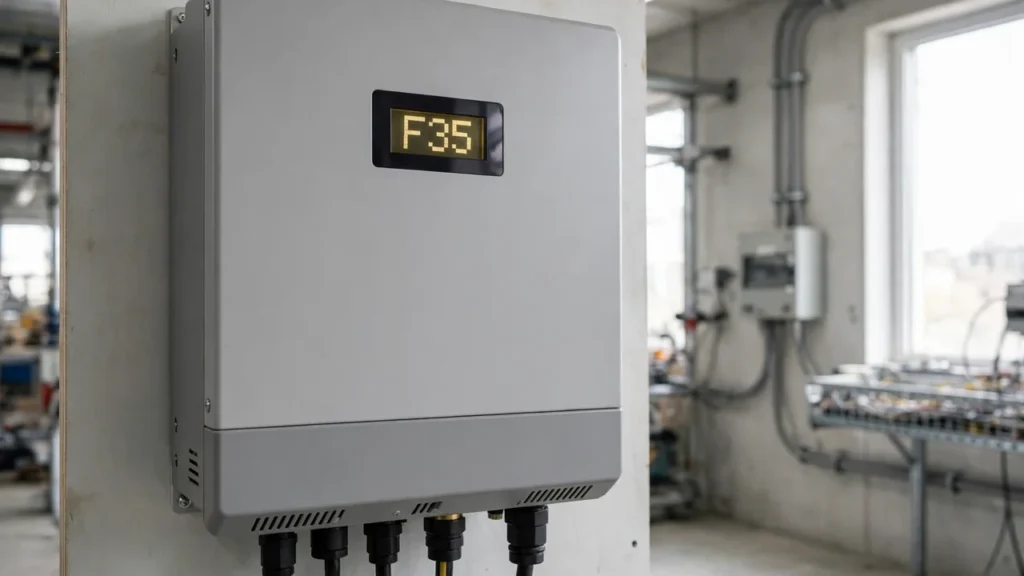
The IRFB4115 is a big, strong version of that switch. It lives in UPS and solar inverter power stages. There, it switches high current again and again, many thousands of times each second.
Why does this matter to you? Because a weak or wrong MOSFET fails fast. It can also damage the driver chip and the board around it. Pick the right part, and your repair lasts. Pick a close-enough part, and the job comes back.
What do the numbers 150V and 104A really mean?
The name tells you a lot, once you know how to read it.
- IRF points back to International Rectifier, the HEXFET pioneer. That business is now part of Infineon.
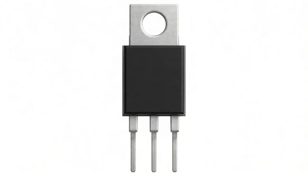
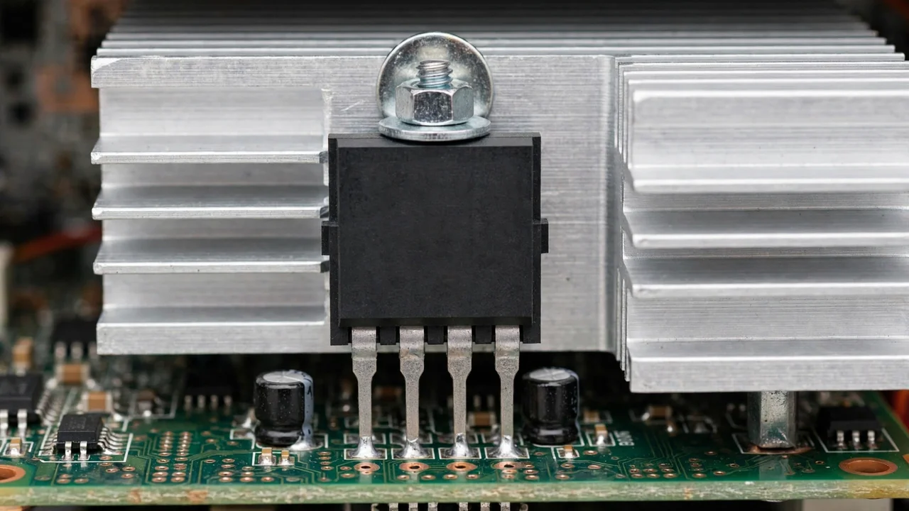
- B means the TO-220AB through-hole package. It is the black plastic part with a metal tab and three legs.
- 4115 is the device number in the family.
- 150V is the highest drain-to-source voltage, called Vdss. Never go above it. In good design, you stay well below it.
- 104A is the highest continuous drain current, but only at a case temperature of 25°C and with a 10V gate drive. At a case temperature of 100°C, that rating drops to 74A.
That last point is the one most people miss. A headline number without its conditions is only half the story. Your inverter does not run at 25°C. It runs hot, inside a box, in a Pakistani summer. So treat the headline with respect, and design for real heat.
IRFB4115 specifications at a glance
All values below come from Infineon’s published IRFB4115 datasheet. If a part you buy acts very differently, question the part, not the datasheet.
| Specification | Value |
|---|---|
| Type | N-channel power MOSFET |
| Package | TO-220AB, through-hole |
| Max drain-to-source voltage (Vdss) | 150V |
| Max gate-to-source voltage (Vgs) | ±20V |
| Gate threshold (Vgs(th)) | 3V to 5V |
| Full gate drive needed | 10V |
| Continuous drain current, 25°C case | 104A |
| Continuous drain current, 100°C case | 74A |
| Pulsed drain current | 420A |
| Max on-resistance (Rds(on)) | 11 milliohms at 10V gate drive, 62A |
| Typical on-resistance | About 9.3 milliohms |
| Max power dissipation, 25°C case | 380W, derated at 2.5W per degree above 25°C |
| Total gate charge, max | 120nC at 10V |
| Input capacitance | 5270pF at 50V drain |
| Operating junction temperature | −55°C to +175°C |
Source: Infineon IRFB4115 datasheet (PDF)
Low on-resistance is why this part exists. At 50 amps, 11 milliohms turns into about 27 watts of heat. That heat must go somewhere. A good heatsink is not optional.
IRFB4115 vs IRFB4110: which one do you need?
These two siblings confuse many buyers. The table makes the choice simple.
| Part | Voltage | Continuous current | On-resistance | Best for |
|---|---|---|---|---|
| IRFB4110 | 100V | Higher (180A, silicon-limited) | About 4.5 milliohms | Lower-voltage systems where current matters most |
| IRFB4115 | 150V | 104A at 25°C case | 11 milliohms max | Systems that need more voltage headroom |
Choose by your system’s voltage first. Do not pick the bigger current number and hope the voltage works out. For the full selection method, read our power MOSFET selection guide.
Where is the IRFB4115 used?
You will find this kind of part in four main jobs:
- UPS inverter stages. The power stage turns battery DC into mains AC. Current is high. Low resistance keeps losses down.
- Solar inverter power stages. The job is similar, with high current and a demand for efficiency. The 150V rating suits 48V battery systems with room for spikes.
- Synchronous rectification in power supplies. Here the MOSFET works as an active rectifier. It wastes far less energy than a diode at high current.
- Motor drives and DC-DC converters. Anywhere high current must switch fast and clean, this device class earns its place.
How can you test an IRFB4115 with a multimeter?
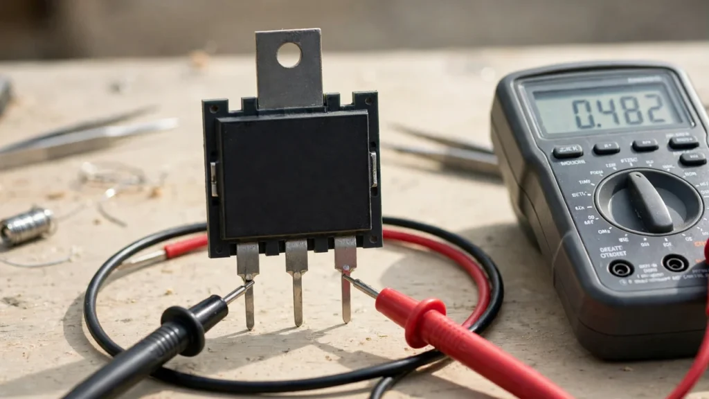
A MOSFET has a built-in body diode. That diode makes testing simple, once you know the steps.
First, find the pins. Hold the TO-220 with the tab away from you and the pins down. From left to right, the pins are gate, drain, source. The metal tab connects to the drain. Always check the datasheet. Never guess a pinout on a power part.
Next, discharge the gate. Short all three pins together for a moment. A charged gate holds the part on and confuses every reading.
Now test the body diode. Put your meter in diode mode. Red probe on source, black on drain. Expect a drop of about 0.4 to 0.7V. Swap the probes. Now expect OL, or open circuit.
Then check gate health. Measure resistance from gate to source, and from gate to drain. Both must read OL. Any low reading means the gate oxide is damaged. The part is dead.
Finally, try the switching test. In diode mode, black on drain and red on source should read OL. Briefly touch the gate to the drain to charge it. Measure drain to source again. It should now read low, a few tenths of a volt. Short gate to source, and it should go back to OL. If it switches like this, the device is alive.
One more habit helps a lot. Test a known-good IRFB4115 next to the suspect one. Compare the readings. Meters vary. A part that reads very differently from its twin deserves suspicion.
How can you spot a fake IRFB4115?
High-current MOSFETs are among the most copied parts in the market. A weak part, relabelled as an IRFB4115, can even pass a simple multimeter test. Then it dies under real load.
Watch for these signs:
- Blurry or weak markings. Genuine laser markings are sharp and hard to scratch off. Cheap ink wipes off with acetone.
- Repeat failures in a good circuit. If new parts keep dying, suspect the parts, not the design.
- High on-resistance. A genuine part meets the 11 milliohm maximum. A fake often reads far higher, if you can measure it.
- A price far below the market. That is not a bargain. It is a warning.
When you replace MOSFETs in a parallel group, replace the full set from the same batch. Mixing old and new parts shares current unevenly. The weakest part then fails first.
How do you install it so it survives?
Four steps protect your repair:
- Fit a heatsink with thermal compound. Clean both surfaces. Use a thin, even layer. Tighten the screw properly. A dry or loose mount cooks the part.
- Insulate the tab where needed. The tab is live at drain voltage. If the heatsink is grounded or shared, use an insulating pad and shoulder washer.
- Check the gate drive. The driver must give clean 10V switching. Many so-called MOSFET failures are really driver failures.
- Check the parts around it. Gate resistors, driver chips, and snubber networks all affect survival. A shorted gate resistor will kill even a perfect MOSFET.
Gate protection matters too. A small 18V zener diode like the BZX84C18 can clamp spikes that would punch through a MOSFET gate. Check those small protection parts whenever power MOSFETs fail again and again.
Frequently asked questions
Can I replace an IRFB4115 with any 150V MOSFET?
No. Voltage is only one number. The replacement must match or beat the current rating. It must have equal or lower on-resistance. It must fit the TO-220 package. And it must work with the existing 10V gate drive.
Is 104 amps realistic in a repair?
It is the datasheet maximum with ideal cooling. In real repair work, treat this part as a very capable 50 to 70 amp device with proper heatsinking. If you need the full 104A all the time, you need serious thermal design.
Why do my MOSFETs keep blowing after replacement?
Work through this list in order: fake parts, a faulty gate driver, the wrong gate drive voltage, shorted parts nearby, poor heatsinking, or an undersized substitute. Do not just fit the same part again and hope.
Where can I buy a genuine IRFB4115 in Pakistan?
SunTech Mall stocks original power MOSFETs for UPS and inverter repair. Check the live price and availability in our electronic parts section, or reach us through the website. You can also message us on WhatsApp via the website for help choosing the right part.
Verdict: should you use the IRFB4115?
Yes, if your circuit needs a strong 150V N-channel switch with low resistance and a real 10V gate drive. It is a proven part for UPS and inverter power stages, backed by a full Infineon datasheet.
Just respect its limits. Keep voltage well below 150V. Cool it properly. Drive its gate at 10V. Test it before you fit it. Do those four things, and this MOSFET will give you a repair that stays repaired.
For more help, read our power MOSFET selection guide, our home solar installation guide, and our hybrid inverter guide. Browse matched parts in our solar energy collection.