


CHOPPER TRANSFORMER TX 401-070044-00G: Essential Component for Solar Inverters
In the rapidly evolving field of renewable energy, solar inverters play a crucial role in converting direct current (DC) generated by solar panels into alternating current (AC) for home and industrial use.…

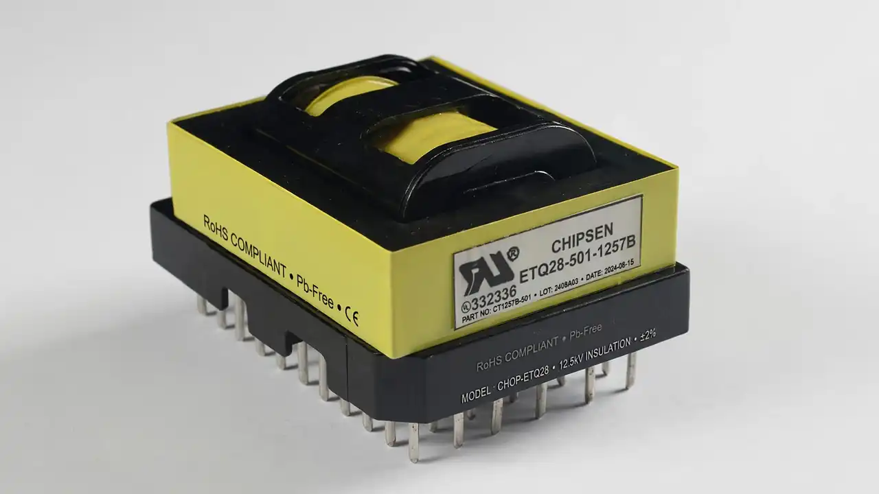
I have seen many solar inverters come back to life with one small part changed. The big MOSFETs get all the attention, but sometimes the real culprit is a small transformer sitting quietly near the control section. When it fails, the whole inverter refuses to start, and most technicians stare at the board for hours.
At SunTech Mall, we supply original electronic components to repair shops across Pakistan. Chopper transformers are among the parts technicians ask about most, because a wrong replacement can waste a whole day. The TX 401-070044-00G is one such part used in solar inverter circuits.
Here is the fear every repair technician knows: you replace the MOSFETs, the capacitors, even the driver IC, and the inverter still shows no sign of life. The standby power section is dead. Money spent, customer waiting, and the fault is still hiding.
In this guide, I will explain exactly what the TX 401-070044-00G chopper transformer does, how to test it with a basic multimeter, how to spot a failing one, and how to replace it correctly. By the end, you will know whether this small part is your problem or not.
Let us start with the most misunderstood thing about this component: what a chopper transformer actually is.
A Quick Note Before You Trust This Guide
You might think this article only exists to sell you a transformer. That is a fair suspicion, so let me clear it now. The testing methods in this guide work with any multimeter, on any brand of inverter, whether you buy the replacement from SunTech Mall or from your local market. My goal is to save you a misdiagnosis, not to push a sale.
In This Guide: What You Will Be Able to Do
- Understand what a chopper transformer does inside a solar inverter
- Know where the TX 401-070044-00G sits in the circuit and why it matters
- Test the transformer with a multimeter in under five minutes
- Recognize the symptoms of a failed chopper transformer
- Tell the difference between a transformer fault and a MOSFET or IC fault
- Replace the part safely without damaging the board
- Avoid the common mistakes technicians make with SMPS transformers
What a Chopper Transformer Actually Does
Most people hear “transformer” and picture the big iron box on a street pole. A chopper transformer is a completely different animal. It is small, light, and works at very high frequencies.
A chopper transformer works inside switch-mode power supplies. Inside your solar inverter, there is a small auxiliary power supply that runs the control circuits, the display, the fans, and the gate drivers. This auxiliary supply switches on and off tens of thousands of times per second. The chopper transformer transfers energy at that high switching frequency.
It uses a ferrite core, not iron. At high frequencies, iron wastes energy as heat. Ferrite, a ceramic magnetic material, handles fast switching with far lower losses. That is why this transformer looks like a small plastic block, not a heavy iron unit.
It provides isolation and voltage conversion together. It delivers safe low voltages to the control side while keeping the dangerous high-voltage section electrically separated. This isolation is a safety requirement.
The TX 401-070044-00G is a part-number-specific component. The “TX” prefix marks it as a transformer, and the number identifies its exact winding ratios, pinout, and core. It is designed for a particular inverter control board. This matters enormously: chopper transformers are not generic parts you can swap freely like resistors.
Note: Never assume similar-looking transformers are interchangeable. Always match the exact part number.
Once you understand its job, the failure symptoms start making sense.
Where It Sits in Your Solar Inverter
Open a hybrid solar inverter and look near the control board. You will usually find the chopper transformer close to a small 8-pin switching IC and one or two power MOSFETs. Together, these form the auxiliary or standby power supply.
This small supply powers everything else. Before the main inverter stage can even wake up, the auxiliary supply must produce its low-voltage rails. If the chopper transformer is dead, there is no standby power, the microcontroller never boots, the display stays dark, and the inverter looks completely dead.
That is why it causes such confusing symptoms. A technician sees a totally dead inverter and starts checking the big power stage. But the big stage was never the problem. The tiny auxiliary supply, and sometimes just this one transformer, was stopping everything.
If you are learning how these power stages are built, our guide on choosing the right power MOSFET explains the switching devices that work alongside transformers like this one.
Signs Your Chopper Transformer Has Failed
A failed chopper transformer does not always look burnt. Here are the real-world symptoms I have seen.
The inverter is completely dead, with no display and no relay click. This is the classic sign. No standby voltages means nothing downstream can start. Before you condemn the main board, check whether the auxiliary supply is producing its outputs.
The switching MOSFET in the auxiliary supply keeps blowing. If you replace the small MOSFET and it burns again within seconds, suspect the transformer. Shorted turns inside the winding draw excessive current and kill the switching device repeatedly.
You hear a faint ticking or chirping from the board. Many SMPS controller ICs enter a restart cycle when the transformer cannot transfer energy properly. The result is an audible tick-tick-tick as the chip tries to start, fails, and retries.
The transformer runs unusually hot or smells burnt. A healthy chopper transformer runs warm at most. If it is too hot to touch or smells of burnt varnish, the windings are likely damaged.
Visible damage: cracked core, melted bobbin, or discolored windings. Ferrite cores are brittle. A cracked core changes the inductance and ruins operation. Look closely under good light.
How to Test the TX 401-070044-00G With a Multimeter
You do not need expensive equipment. A basic digital multimeter covers the essential checks.
Step 1: Disconnect power and discharge the capacitors. Safety first. Unplug the inverter, wait several minutes, and verify the high-voltage DC bus capacitors are discharged with your meter. Never work on a live board.
Step 2: Identify the windings. Look at the transformer pins. A chopper transformer has at least two windings: primary and secondary, sometimes with an auxiliary feedback winding. Pins belonging to the same winding will show low resistance between each other, typically from a fraction of an ohm to a few ohms.
Step 3: Check continuity of each winding. Set your meter to resistance or continuity mode. Measure between pin pairs. Each winding should show a low, stable resistance. An open reading (OL) on a winding means a broken wire inside, and the transformer must be replaced.
Step 4: Check isolation between windings. Measure resistance between a primary pin and a secondary pin. It must read open (OL), meaning infinite resistance. Any measurable resistance between windings indicates an insulation breakdown, which is dangerous and means immediate replacement.
Step 5: Check for shorts to the core. If the core is exposed metal, measure from any winding pin to the core. This must also read open.
Step 6: Compare readings if you have a known-good board. The most reliable test is comparison. If another identical inverter is available, measure the same pins on its transformer. A winding that reads very different resistance has likely developed shorted turns.
For more on systematic fault-finding in inverter circuits, see our electronic parts guides covering the components most often involved in these failures.
Why Chopper Transformers Fail in Pakistan
Understanding the causes helps you prevent repeat failures.
Heat is the biggest killer. Inverter rooms in Pakistan often cross 45 degrees in summer. Heat degrades the winding insulation over time. A transformer that would last a decade in cool conditions may fail in a few years in a hot, poorly ventilated installation.
Voltage surges stress the insulation. Grid fluctuations and lightning-induced surges can punch through winding insulation. Once a single turn shorts, the failure cascades.
Overload of the auxiliary supply. If someone modifies the board or adds extra load to the auxiliary rails, the transformer runs beyond its design. It overheats and fails early.
Poor soldering and vibration. Cracked solder joints at the transformer pins cause arcing, which damages both the pins and the winding ends. In areas with vibration, this is more common than people expect.
Replacing the TX 401-070044-00G Correctly
Replacement is straightforward, but the details matter.
Match the exact part number. Order the TX 401-070044-00G specifically, not a “similar” transformer. Pinout and winding ratios must match the board design.
Use proper desoldering technique. Chopper transformers have multiple thick pins. Use a desoldering pump or wick, and heat each joint fully before pulling. Forcing the part can lift PCB pads, turning a simple repair into a board-level nightmare.
Check the surrounding components before powering up. The switching MOSFET, the controller IC, the rectifier diodes, and the output capacitors in the auxiliary supply should all be tested. A failed transformer often takes one of these with it. Powering up with a shorted diode will just kill your new transformer.
Verify output voltages after replacement. Before reconnecting everything, power the board and measure the auxiliary rails. They should match the expected values marked on the board or in the service manual. Only then reassemble.
You can find original replacement components in our electronic parts section, where we stock genuine parts for inverter repair.
Common Mistakes Technicians Make
Mistake 1: Rewinding the transformer by hand. Some technicians try to rewind a failed chopper transformer. Unless you know the exact turns count, wire gauge, and winding arrangement, the result will not match the original. For a part-number-specific component, replacement beats rewinding.
Mistake 2: Ignoring the cause of failure. If heat killed the first transformer, the replacement will die too unless ventilation improves. Always ask why it failed.
Mistake 3: Testing in-circuit and trusting the readings. Parallel components on the board distort resistance measurements. For a definitive test, desolder at least one side of the winding or lift the transformer fully.
Related guides: IRFB4115 MOSFET for the switching devices in these supplies, UF5M diode guide for fast rectifiers, MOSFET selection, and electronic parts.
See also: zener diode, wind turbine, installation guide, home.
Frequently Asked Questions
Can I use any chopper transformer as a replacement for the TX 401-070044-00G?
No. Chopper transformers are designed for specific circuits with particular winding ratios, inductance values, and pinouts. Always replace with the exact part number. A wrong transformer can prevent startup or damage the switching IC.
How do I know if the transformer or the switching IC is at fault?
Test the transformer windings first with the multimeter checks in this guide. If all windings show correct continuity and isolation, the IC or its surrounding components are more likely at fault. The ticking restart symptom points to either, so testing narrows it down.
What causes a chopper transformer to burn repeatedly?
Usually an unresolved overload or a short elsewhere in the auxiliary supply, such as a shorted output diode or capacitor. Replacing the transformer without fixing the root cause leads to repeat failure. Also check for excessive ambient heat.
Can a multimeter detect shorted turns inside the transformer?
Partially. A winding with shorted turns often shows lower resistance than a good one, but the difference can be small. The most reliable multimeter method is comparing readings against a known-good transformer of the same part number.
Is the TX 401-070044-00G repairable if a wire breaks at the pin?
If the break is right at the pin and you can see clean wire ends, a careful resolder can work. But if the break is inside the winding, replacement is the practical answer. Do not unwind the coil hoping to find it.
Why does my inverter tick but not start?
Ticking usually means the SMPS controller is trying to start and hitting overcurrent or undervoltage protection, then retrying. A faulty chopper transformer is one common cause, but so are shorted output diodes and failed capacitors. Test systematically.
Where can I buy a genuine TX 401-070044-00G in Pakistan?
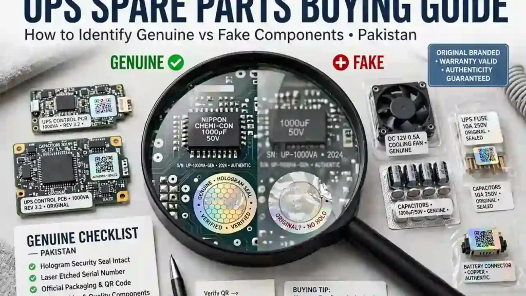
Check the current availability on SunTech Mall’s website, where we list original components for solar inverter repair. Buying genuine matters here because winding specifications cannot be verified visually. You can reach us at info@suntechmall.com or +92 306 2244820.
Final Thoughts
The TX 401-070044-00G is small, but it carries a big responsibility. It wakes up the entire inverter. When it fails, everything downstream goes silent, and the symptoms mislead even experienced technicians toward the big power stage.
You now know what this chopper transformer does, where it lives in the circuit, how to test it with a simple multimeter, and how to replace it without creating new problems. That knowledge turns a mysterious dead inverter into a solvable, routine repair.
Congratulations on adding a genuinely useful diagnostic skill to your toolkit. Most technicians skip the auxiliary supply entirely. You will not.
If you need a genuine replacement or advice on a tricky board, SunTech Mall is here to help. Browse our electronic parts collection or contact us at info@suntechmall.com. Good luck with your next repair.

1 Comment
[…] devices these diodes protect, the BZX84C18 zener guide explains small-signal protection, and the chopper transformer article shows where fast diodes work in auxiliary supplies. For system-level context, see why hybrids suit […]