



TLP250H Optocoupler: A Simple Guide to Specs, Wiring and Real-World Use
The TLP250H Optocoupler is a high-speed gate driver designed to provide electrical isolation between low-power control circuits and high-power switching devices such as MOSFETs and IGBTs. This optocoupler is widely used in…

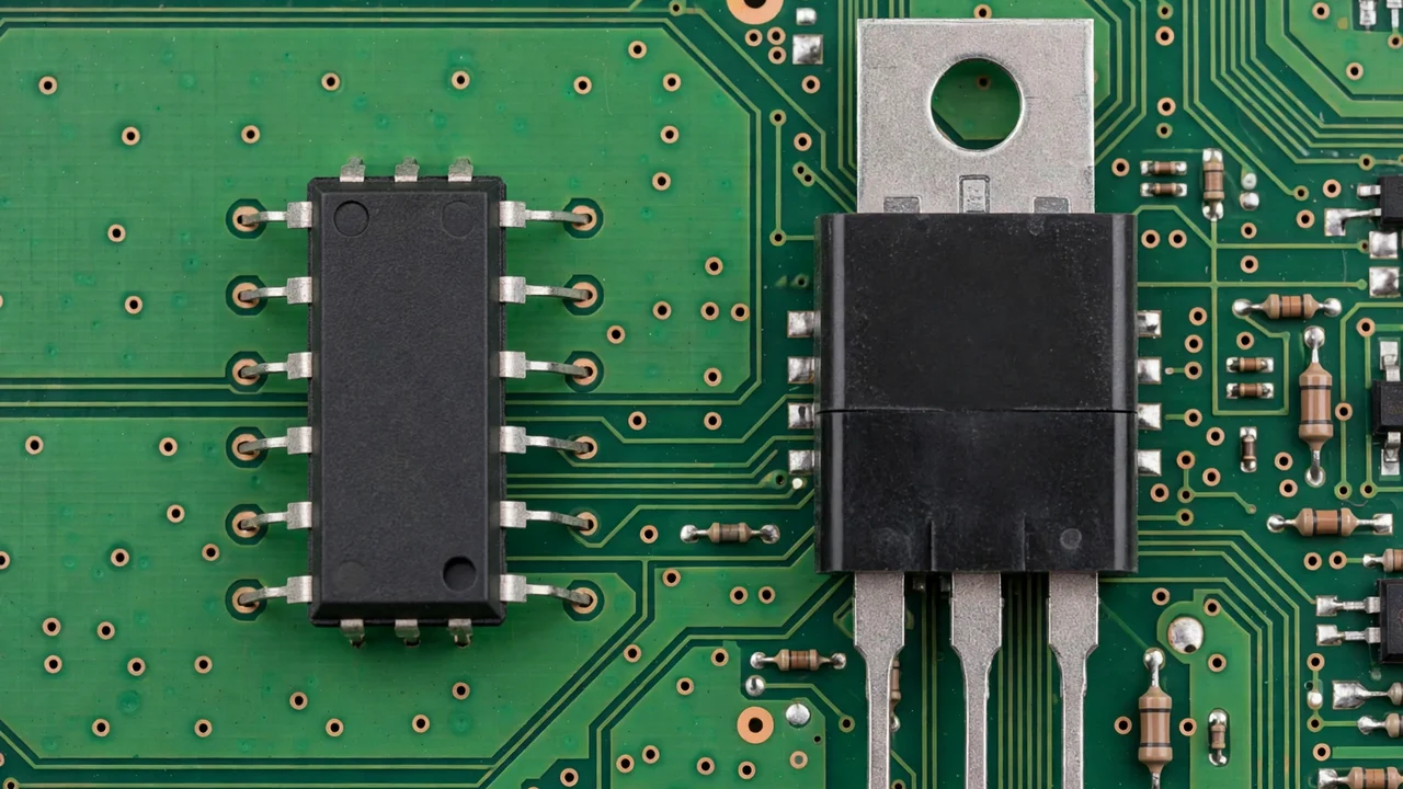
Dek: This guide explains what the TLP250H gate driver optocoupler does, what its specs mean in plain words, and how to wire it without burning your power transistors.
Key takeaways
- The TLP250H is a gate driver optocoupler. It drives MOSFET and IGBT gates with strong, fast pulses, while keeping the control side electrically separate from the power side.
- Its headline specs are a ±2.5 A peak output, a 10–30 V supply, 500 ns maximum delay, and 3,750 Vrms minimum isolation.
- It fits inverters, motor drives, UPS systems and power supplies. It is not the right pick for the very largest IGBT modules or very-high-frequency designs.
- Check the live price on the website. Always confirm the specs against the datasheet of the exact part you buy.
In this guide: What it does · Specs in plain words · How to wire it · Where it works best · Honest review · Comparison · Repair tips · FAQ · Verdict
What does a TLP250H gate driver optocoupler do?
A power MOSFET or IGBT gate acts like a big capacitor. To switch it fast, you must push current into that gate and pull it back out again, thousands of times each second. A microcontroller pin is far too weak for that job.
The TLP250H is the muscle in between. A small control signal goes in. A strong gate drive comes out. Inside the chip, an LED shines on a light sensor. The signal crosses as light, so there is no direct electrical link between the two sides. That link is called galvanic isolation.
Why does that matter? In an inverter or motor drive, the power side swings by hundreds of volts each cycle. Without isolation, that noise can rush back into your control circuit. With the TLP250H barrier in place, each side lives in its own electrical world.
Note: Not every optocoupler can drive a power transistor. A small signal optocoupler only passes a tiny signal. The TLP250H is a driver type, built to source and sink heavy gate current. Do not swap one for the other.
What do the TLP250H specs mean in plain words?
These figures come from the Toshiba TLP250H datasheet. Treat them as the H version’s specs, not the older TLP250’s. Always check the datasheet of the exact part in your hand.
| Spec | TLP250H figure | What it means for you |
|---|---|---|
| Peak output current | ±2.5 A max | Strong enough to switch medium and fairly large MOSFETs and IGBTs briskly |
| Supply voltage (Vcc) | 10–30 V | The output side needs its own supply; 15 V is the classic choice for IGBTs |
| Delay (propagation) | 500 ns max | Half a microsecond from input to output; fine for most inverter and drive frequencies |
| Isolation voltage | 3,750 Vrms min | A strong barrier between the control side and the power side |
| Temperature range | −40 °C to 125 °C | Built to survive inside hot equipment |
| Package | DIP-8 | An 8-pin through-hole chip that is easy to socket, probe and replace |
| Input threshold current | 5 mA max | The LED input needs only a small current to switch |
A note on the old article: it quoted 1.5 A and 2,500 Vrms. Those are the older TLP250’s figures, not the TLP250H’s. This rewrite corrects them to the H datasheet values above. (Source: Toshiba TLP250H datasheet)
How do you wire the TLP250H?
Here is a standard MOSFET driving circuit, pin by pin.
Input side. Pin 2 is the LED anode and pin 3 is the cathode. Your control signal drives the anode through a current-limiting resistor, with the cathode to control-side ground. A resistor near 1 kΩ is a common starting value for 5 V logic, but you must work out the value for your own logic level and LED current.
Output side. Pin 8 takes the driver supply, often 12–24 V. Pin 5 is output-side ground. Pins 6 and 7 are the output. The output connects to the MOSFET gate through a small gate resistor. A value near 10 Ω is a common starting point. It damps ringing and controls switching speed, which affects heat and electrical noise.
Two details that separate working circuits from flaky ones:
- Decouple the output supply. Put a ceramic capacitor right at pins 8 and 5. The driver gulps current in sharp pulses, and long supply traces starve it.
- Add a gate-to-source pulldown resistor. A value near 100 kΩ keeps the MOSFET firmly off if the driver ever loses power. A floating gate in a power circuit is dangerous.
Keep the loop from driver output, through the gate resistor, to the gate and back as short and tight as you can. Extra trace length adds inductance, slows switching and invites ringing.
For clean supply rails around the driver, see our 50V 4.7nF SMD capacitor guide.
Where does the TLP250H work best?
Solar inverters. An inverter bridge switches DC into AC through four or more power transistors. Each one needs isolated, muscular gate drive. One TLP250H per transistor, each on its own isolated supply, is a natural fit.
Motor drives. Variable-frequency drives switch IGBTs or MOSFETs at high frequency to shape motor current. Fast, clean gate drive means cool transistors. Weak drive means heat and early death.
UPS systems. A UPS inverter does the same bridge job as a solar inverter: battery DC to mains AC, fast. The same driver rules apply.
Switching power supplies. Higher-power supplies use discrete MOSFETs or IGBTs on the primary side. Those need real gate drive with isolation from the control circuit. The TLP250H fits well, above all in half-bridge and full-bridge designs.
Is the TLP250H a good part? An honest review
Strengths. The isolation barrier is strong and properly rated. The 2.5 A peak drive covers a wide middle range of devices with authority. The speed suits the frequencies real inverters and drives actually use. The wide supply and temperature ranges make it forgiving. And the DIP-8 package is a gift to repair technicians: socket it, probe it, swap it.
Limits. The largest IGBT modules want dedicated high-current drivers. The 500 ns delay rules it out of very-high-frequency designs. And each high-side driver in a bridge needs its own isolated supply, which adds design work.
None of these limits are flaws. They are the edges of the part’s intended territory. Inside that territory, it is a reliable classic.
How does the TLP250H compare?
| Part | Best for | Key difference |
|---|---|---|
| TLP250H | Medium to fairly large MOSFETs and IGBTs | ±2.5 A peak, 3,750 Vrms isolation, DIP-8 |
| TLP250 (older, non-H) | Smaller gate-drive jobs | ±1.5 A peak, 2,500 Vrms isolation — do not confuse it with the H version |
| Signal optocoupler | Passing small signals only | Cannot source gate current; never use it as a gate driver |
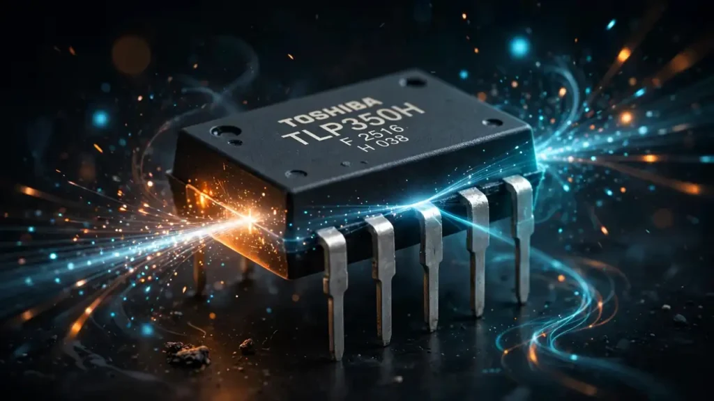
| TLP350H | Larger gate-drive jobs | A bigger sibling in the same family; see our TLP350H optocoupler guide for its own specs |
Choose by gate charge, not by habit. For protection on the rails feeding these drivers, a part like the BZT52C39V zener diode is the kind of small guardian that belongs in the same design.
What should you check when transistors keep failing?
Most failures I hear about are layout or driver failures, not bad transistors. Work through this list before you replace the power devices again:
- Keep input and output grounds separate. Copper that sneaks across the isolation barrier defeats the whole point of the part.
- Mind creepage and clearance under and around the package.
- Decouple hard on the output side.
- Size the gate resistor on purpose. Too small gives ringing and noise. Too large slows switching and heats the transistor. Ten ohms is a starting point, not a law.
- Test the driver first. Check the output supply voltage under load, look at the gate waveform shape and size, and confirm the gate resistor’s value.
If you need to test a power transistor itself, our guide on how to test a MOSFET with a multimeter walks through it step by step.
Frequently asked questions
Can the TLP250H drive IGBTs directly?
Yes, that is one of its main jobs. It works when the IGBT’s gate charge fits what 2.5 A peak can switch at your frequency. Roughly, average drive current equals gate charge times switching frequency. If the numbers fit with margin, direct drive is exactly what this part is for.
What supply voltage should I use on the output side?
About 15 V is the classic choice for IGBTs. The part accepts 10–30 V, so 12–18 V covers most jobs well. Never run it below about 10 V. Under-driven gates switch slowly, and slow switching cooks transistors.
Why do my MOSFETs run hot even though the driver is new?
Heat means slow or incomplete switching. Check in order: gate resistor too large, driver supply sagging under load, input LED current too low, or too much inductance in the gate loop. Measure the full supply voltage at the driver’s pins while it is switching, not just at idle.
Can I use one TLP250H for the high side of a bridge?
Yes, but the high-side driver needs its own floating supply, referenced to the switching node. Bootstrap supplies or small isolated DC-DC converters per high-side driver are the standard way to do this.
Where can I buy a genuine TLP250H in Pakistan?
Gate drivers are exactly the parts where fakes cause the most expensive damage, because a fake driver kills the transistors it should protect. SunTech Mall stocks the TLP250H gate driver optocoupler for inverter, UPS and motor drive repair across Pakistan. Check the live price on the website, or reach us on WhatsApp.
Verdict
You now know what a gate driver optocoupler does, what the TLP250H’s specs mean, how to wire it pin by pin, and where its honest limits sit. Most of all, you now suspect the driver stage first when transistors keep dying.
That one habit saves more boards than any other. Gate drive is an invisible art: when it is right, nobody notices; when it is wrong, everything burns. Now you notice.
Related reading: TL431 shunt regulator guide · BZT52C39V zener diode guide · 0 ohm SMD resistor guide · Shop all products
Sources: Toshiba TLP250H datasheet (Mouser) · Toshiba TLP250 datasheet for the non-H comparison
1 Comment
[…] parts collection for genuine 0 ohm resistors, precision passives, and the driver ICs like our TLP250H gate driver optocoupler that keep Pakistan’s repair shops running. Questions about a specific board? Email […]