


TL431 Shunt Regulator: How to Set Any Voltage from 2.5V to 36V
The TL431 SMD Precision Shunt Regulator is a compact yet powerful component essential for voltage regulation in various electronic circuits. With adjustable voltage from 2.5V to 36V, high precision, and excellent thermal…

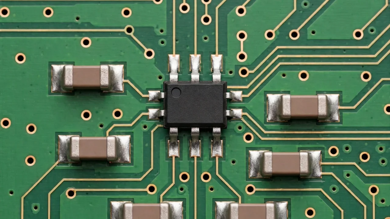
Dek: This guide explains how the TL431 works, how two resistors set any voltage you want, and why it sits beside an optocoupler in almost every switch-mode power supply.
Key takeaways
- The TL431 is a programmable voltage reference. It acts like an adjustable zener diode with a built-in amplifier watching over it.
- Two resistors set any voltage from about 2.5 V up to 36 V, using one formula: Vout = 2.495 V × (1 + R1 ÷ R2).
- Its internal reference is 2.495 V typical, its cathode current range is about 1–100 mA, and its typical dynamic impedance is 0.22 Ω.
- In a switch-mode supply, the TL431 watches the output and drives an optocoupler LED, closing the feedback loop across the isolation barrier.
- Check the live price on the website. Always confirm the grade and specs against your maker’s datasheet.
In this guide: What it is · Specs in plain words · The divider formula · SMPS feedback · Where else it is used · Mistakes · FAQ · Verdict
What is the TL431?
Forget the long name for a moment. The TL431 is a programmable voltage reference. Think of it as a super-accurate, adjustable zener diode with a built-in amplifier watching over it. You give it two resistors, and it holds the voltage across itself at whatever level those resistors program.
The magic number inside is 2.495 V typical. The TL431 constantly compares a divided-down sample of its own voltage against this internal reference. If the voltage tries to rise, it conducts more current and pulls it back down. If it tries to fall, it conducts less. That continuous correction is what “shunt regulation” means: it shunts extra current away to hold the voltage steady.
Why did this part conquer the world? Three reasons. It is cheap. It is accurate, with grades from about 0.5% to 2%. And it is flexible: one part number covers countless voltage needs. You will find it in SOT-23, SOP-8 and TO-92 packages. The SMD versions ride through pick-and-place machines on modern boards.
Note: “Shunt” confuses beginners. It does not mean the part is broken or shorted. It means the regulator works by diverting current, unlike a series regulator that sits in line with the load. Different technique, same goal: steady voltage.
What do the TL431 specs mean?
| Spec | Figure | What it means for you |
|---|---|---|
| Adjustable output | About 2.5 V to 36 V | One part can serve as a 3.3 V, 5 V or 12 V reference — just change two resistors |
| Internal reference | 2.495 V typical | The fixed number your divider math is built on |
| Reference accuracy | About 0.5% (best grade) to 2% (standard grade) | Check the grade suffix on the part you actually bought |
| Cathode current | About 1–100 mA | It sips current at idle but can shunt serious current when correcting |
| Dynamic impedance | About 0.22 Ω typical | It reacts stiffly against load changes and holds the voltage firm |
| Temperature range | Depends on grade, up to −40 °C to 125 °C | Check your grade; not every version covers the full range |
| Packages | SOT-23, SOP-8, TO-92 | Same part electrically; the package only changes mounting and heat handling |
Sources: Texas Instruments TL431 product data and the ON Semiconductor TL431 datasheet.
How do you set the output voltage?
Here is the whole programming method in one line:
Vout = 2.495 V × (1 + R1 ÷ R2)
R1 is the upper resistor, from the output to the reference pin. R2 is the lower resistor, from the reference pin to ground. In practice, most people just use 2.5 V in the math. It is close enough for nearly every job.
| Wanted output | Math | Resistors to use |
|---|---|---|
| 5 V | 2.5 × (1 + 10k ÷ 10k) = 5 V | R1 = 10 kΩ, R2 = 10 kΩ |
| 3.3 V | 2.5 × (1 + 3.3k ÷ 10k) = 3.3 V | R1 = 3.3 kΩ, R2 = 10 kΩ |
| 12 V | 2.5 × (1 + 39k ÷ 10k) = 12.25 V, close to 12 V | R1 = 39 kΩ, R2 = 10 kΩ (nearest standard value) |
That is it. The formula never changes. Only the two resistors change.
Bonus tip: Keep the divider current around ten times the reference pin’s input current, so the divider is “stiff” and accurate. Resistor values in the 10 kΩ range work well for most TL431 circuits. Very high values, in the megohm range, invite noise and leakage errors.
One more practical detail: the TL431 needs a minimum cathode current of about 1 mA to regulate properly. Starve it below that and the reference goes soft. When you design the supply resistor feeding it, make sure at least 1 mA flows through the TL431 under all conditions, with comfortable margin. This single oversight causes more “mysterious drift” complaints than anything else.
For clean power around the reference, see our 50V 4.7nF SMD capacitor guide.
Why do the TL431 and optocoupler always appear together?
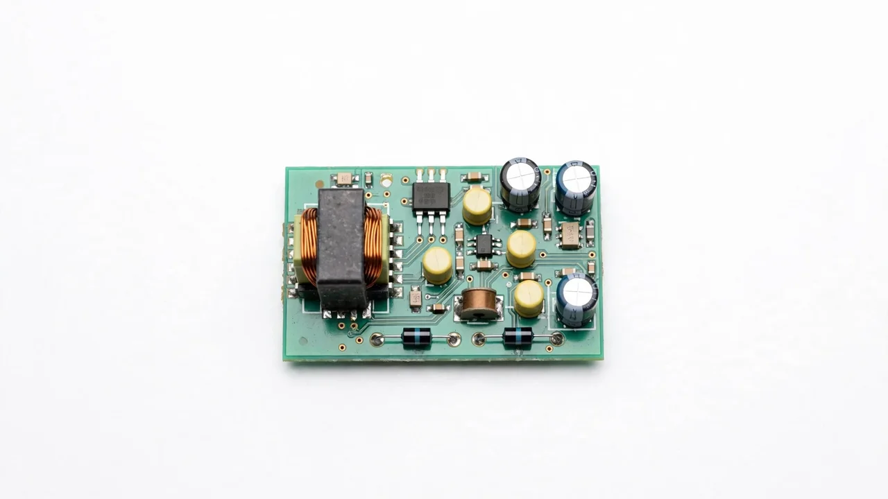
This is the application that made the TL431 famous. In a switch-mode power supply, the high-voltage primary side must be electrically isolated from the low-voltage output side, for safety. But the control chip on the primary side still needs to know what the output voltage is doing. How do you send that information across an isolation barrier?
With light. The TL431 sits on the output side, watching the voltage through its divider. When the output rises too high, the TL431 conducts harder, driving current through the LED inside an optocoupler. The light signal crosses the barrier and tells the primary-side controller to back off. Output falls, the TL431 conducts less, the LED dims, and the controller pushes harder. A closed loop, running in millions of chargers and adapters worldwide.
This is why, when a charger has no output or the wrong output voltage, experienced technicians check the TL431 and the optocoupler together. They are a team. If you work on power supplies, our TLP250H gate driver optocoupler guide covers the bigger optocouplers that drive power transistors on the high-power side of similar equipment.
Note: When troubleshooting a dead supply, do not replace only the obviously burnt parts. Test the TL431 with a simple divider and a power supply: feed the cathode through a resistor, set the divider for a known voltage, and check that the cathode clamps at that voltage. A thirty-second test that saves hours.
Where else is the TL431 used?
Battery chargers and charge control. Chargers need precise voltage limits to avoid overcharging batteries. The TL431’s sharp, accurate threshold makes it ideal for setting charge termination voltage or driving the charger’s own feedback stage.
Voltage monitoring. Need a circuit that notices when a rail rises above 12 V or falls below 5 V? A TL431 with a divider becomes a precision voltage monitor. Its output can drive an LED, a transistor or a microcontroller input. Simple, accurate, and far cheaper than a dedicated supervisor chip for many jobs.
Precision voltage references. ADC circuits, sensor interfaces and measurement equipment all need a stable reference. The TL431’s low drift and low noise make it a solid choice, above all where a 2.5 V or adjustable reference is needed on a budget.
Inverter and industrial auxiliary circuits. Inside solar inverters and UPS systems, low-voltage control rails need the same regulation and monitoring as anywhere else. For overvoltage clamping on the higher rails, a part like the BZT52C39V zener diode handles jobs the TL431’s 36 V ceiling cannot reach.
Adjustable zener replacement. Anywhere you might use a fixed zener but wish you could fine-tune the voltage, the TL431 is the upgrade. Two resistors replace an entire drawer of zener values.
Which mistakes make TL431 circuits misbehave?
Mistake one: starving the cathode current. Below about 1 mA the part cannot regulate. Always verify minimum current under worst-case conditions, not just typical ones.
Mistake two: divider resistors too large. Megohm dividers pick up noise and leak, making the output jittery. Stay in the 10 kΩ range unless you have a specific reason not to.
Mistake three: forgetting stability compensation. In feedback loops, the TL431’s internal amplifier can oscillate without proper compensation capacitance. Follow the datasheet’s compensation guidance for your topology. An oscillating TL431 looks like random output ripple.
Mistake four: assuming all grades are equal. A 2% grade part in a circuit designed around 0.5% accuracy will not hold the tolerance you calculated. Check the grade suffix on the part you actually bought.
Mistake five: buying counterfeits. Fake TL431s with sloppy references are depressingly common. They drift, they oscillate, and they waste your debugging time. Source matters enormously for precision parts.
Frequently asked questions
What is the difference between the TL431 and a normal zener diode?
A zener diode has one fixed voltage set at the factory. The TL431 is programmable: two external resistors set any voltage from about 2.5 V to 36 V. It is also far more accurate and stable, thanks to its internal reference and amplifier.
Can I use the TL431 as a 3.3 V reference?
Yes, easily. Set the divider ratio so the formula gives 3.3 V: you need (1 + R1 ÷ R2) = 1.32, so R1 ÷ R2 = 0.32. With R2 = 10 kΩ, R1 = 3.3 kΩ works. Feed the cathode through a resistor from a higher supply, ensure at least 1 mA flows, and you have a solid 3.3 V reference.
Why does my TL431 circuit oscillate?
Almost always a compensation issue. The TL431 contains a high-gain amplifier, and in a feedback loop it needs the right capacitive loading to stay stable. Follow the datasheet’s compensation recommendations, keep divider resistors in sensible ranges, and keep the layout tight with good decoupling nearby.
What packages does the TL431 come in?
The classic through-hole TO-92, plus SMD options including SOT-23 and SOP-8. Electrically they are the same part. The package only changes mounting and power handling. For new SMD designs, SOT-23 is the most common choice.
Where can I buy a genuine TL431 in Pakistan?
Precision parts are exactly where counterfeits hurt most, so buy from a supplier that guarantees genuine stock. SunTech Mall stocks the TL431 in SOP-8, SOT-23 and TO-92 for repair shops and manufacturers across Pakistan. Check the live price on the website, or reach us on WhatsApp.
Verdict
Look at what you can do now. You understand the shunt regulation idea, you can run the divider math in your head, you know why the TL431 and optocoupler are partners in every switch-mode supply, and you know the five mistakes that waste everyone’s debugging time. That is working knowledge, not trivia.
You have just mastered a part that sits inside millions of devices around you right now. The next time a charger or power supply misbehaves, you will look at that little three-pin part with the confidence of someone who knows exactly what it is doing.
Related reading: TLP250H gate driver guide · BZT52C39V zener diode guide · 0 ohm SMD resistor guide · Shop all products
Sources: Texas Instruments TL431 product data · ON Semiconductor TL431 datasheet