
How Do You Read, Test, and Solder a 30 Ohm 1206 SMD Resistor?
If you're working on solar energy systems or compact electronics, choosing the right components is crucial for performance and reliability. One essential element often used in these systems is the 30 ohm…

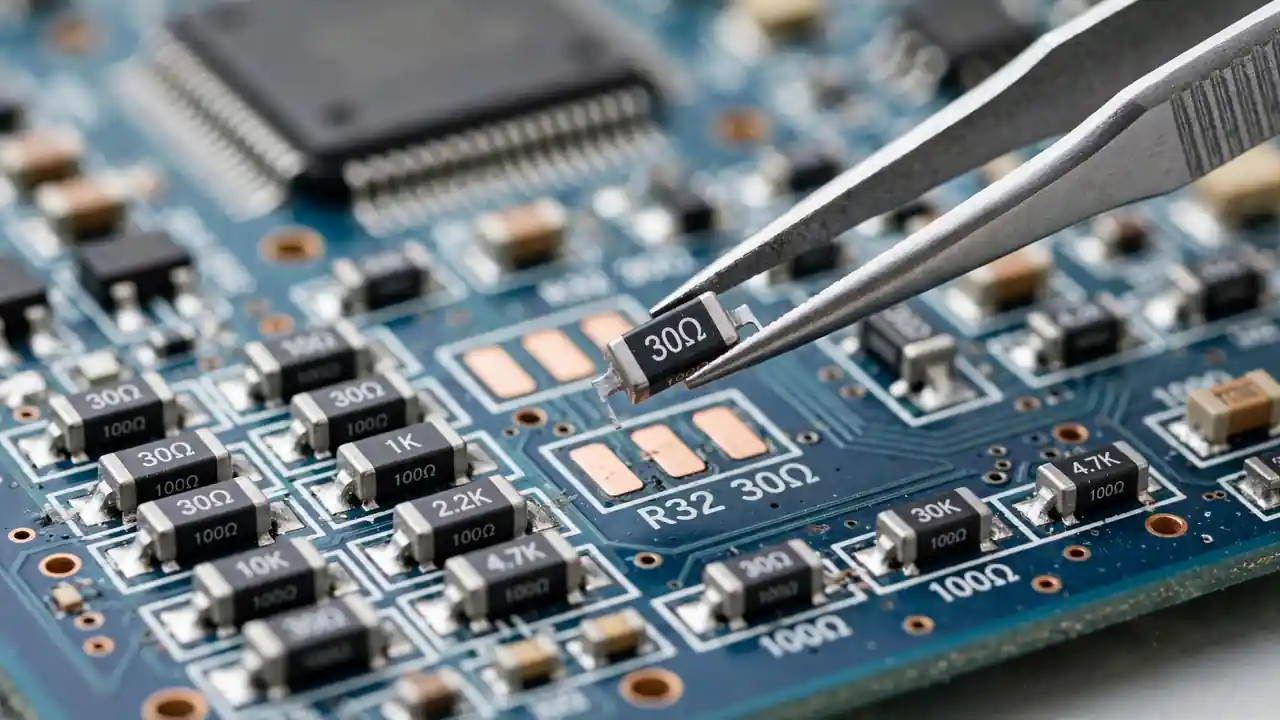
A 30 ohm 1206 resistor is a small chip part, 3.2 mm long and 1.6 mm wide, rated at 0.25W with 1 percent tolerance. You read its value from the code on its top, test it with a multimeter out of circuit, and solder it by tinning one pad first. This guide shows each step in plain words, so you can handle the part without losing it, cooking it, or trusting a false reading.
What does 30 ohm 0.25W 1206 1% mean?
Each part of the name answers a different question. Read them one at a time, and the part stops looking like a code.
| Part of the name | What it means | What it means for you |
|---|---|---|
| 30 ohm | The resistance value | A low value, used where current must be sensed, limited, or damped |
| 0.25W | The power rating | The most heat it can shed without damage; stay well below it |
| 1206, also written 3216 | The package size | 3.2 mm by 1.6 mm; large enough to hand-solder with tweezers |
| 1% | The tolerance | A new part must read between 29.7 and 30.3 ohms |
Power is the limit that bites first on a low-value part. Power follows the rule P equals I squared times R. Put 0.1 amp through 30 ohms and you get 0.3W, which is already above the 0.25W rating. That single sum explains why a small resistor can run hot in a circuit that looks harmless. A good workshop habit is to keep steady dissipation well below the rating, around half to two-thirds of it, and to check the real current before you blame the part.
What code will you see printed on the part?
A 1 percent 1206 resistor often carries the code 30R0. The letter R marks the decimal point, so 30R0 means 30.0 ohms. This R style avoids a tiny decimal dot that is easy to misread under a magnifier. Some makers use a different system for small 1 percent parts, with two digits and a letter for the multiplier. The system varies by maker, so treat the printed code as a hint and the meter as the verdict. Never guess from a blurry mark when a measurement takes seconds.
Put the part code-side up when you fit it. The code side does not change how the resistor works, but the next person who opens the board, who may be you, will thank you. A part fitted face down hides its own identity.
Where is a 30 ohm resistor used?
Thirty ohms is low, so it shows up where current matters more than voltage drop. In current sensing, a low-value resistor sits in series with a power path, and the small voltage across it tells the control circuit how much current flows. The rule is V equals I times R. Note the limit, though: at 1 amp, 30 ohms would drop 30V, which is far too much for most sense circuits. So 30 ohm sensing turns up in lower-current branches, such as auxiliary supplies, fan circuits, and standby rails, not in the main high-current path.
Gate drive damping is a second home. Power transistors sometimes need a series resistor in the tens of ohms to calm ringing and set switching speed. If you find a 30 ohm 1206 close to a power transistor gate pin, damping is a likely job. A third home is a divider or feedback network, where two resistors set a voltage. Here the 1 percent tolerance earns its keep. A 5 percent part in the same spot would shift the divided voltage enough to matter.
Warmth alone does not prove failure. Some low-value resistors run warm by design, for example where they limit inrush current when a capacitor charges at power-on. Judge the part by its reading and by the circuit, not by touch alone.
How do you test it without fooling yourself?
Test out of circuit when you need a verdict you can trust. Set the meter to ohms, touch the probes to the two ends, and expect 29.7 to 30.3 ohms. An open reading, shown as OL, means the part has failed open, which is the most common chip resistor failure after overload. A reading far above 30 ohms means drift or damage.
Two traps catch beginners. The first is lead resistance. Test leads often add 0.1 to 0.3 ohms, which matters when you measure 30 ohms. Short the probes together, press the REL or zero button if your meter has one, then measure. Without that step, a perfect 30.0 ohm part can read 30.2 ohms and look out of tolerance.
The second trap is in-circuit testing. A resistor still soldered to a board sits in parallel with everything wired across it, and those other paths pull the reading low. A correct in-circuit reading is reassuring, but a wrong one proves nothing on its own. Lift one end and measure again before you condemn the part.
Follow these steps for a clean test:
- Remove the part, or lift one end, so no parallel path can corrupt the reading.
- Short the probes and zero the meter with REL, if your meter offers it.
- Measure across the part and wait for a steady reading.
- Compare with 29.7 to 30.3 ohms, and check the body for cracks or dark marks.
- If the reading is open or far off, check the circuit for a downstream short before you fit a new part.
How do you hand-solder a 1206 part?
You do not need a rework station for 1206. A decent iron, fine solder, flux, tweezers, and a magnifier will do. Tin one pad first with a small dome of solder, not a blob. Hold the resistor with tweezers, place it over the pads, and touch the iron to the tinned pad. When the solder melts, the end sinks in. Hold still for a couple of seconds while the joint sets. The part is now tacked in place and will not move.
Then solder the second end. Touch the iron to pad and end together, feed a small amount of solder, and lift the iron away. Check both joints under magnification. Good joints look shiny with a smooth concave fillet, and they do not bridge to neighbours. Work fast, a few seconds per joint. Long heat can crack the ceramic body or harm the ends. If a joint will not flow, add flux rather than adding time.
If the old part failed from overload, find the cause before you fit the new one. A burned, cracked, or open resistor is often the victim of a shorted transistor or capacitor further down the line. A new part in a circuit that killed the old one will die the same way.
What do failure signs tell you?
An open reading is the standard failure. Overcurrent fuses the resistive element, or sustained overload heats it until it breaks. Look for dark marks or a visible crack. Drift upward is the slower failure. Chronic heat nudges the value high, so a 30 ohm part reads 35 or 40 ohms. In a sensing job, that drift makes the circuit think current is higher than it is, which can trip protection for no real reason.
Cracked bodies are a third failure, caused by board flex or a knock. A cracked chip can read correctly at rest and go open with the smallest vibration, which makes the fault come and go. A fourth look-alike is a cracked or cold solder joint. The joint reads open or intermittent, while the resistor itself is fine. Reflowing the joints is worth trying before you replace the part, because sometimes the joint is guilty and the resistor is innocent.
Frequently Asked Questions
Can I replace a 1206 part with a through-hole resistor? Electrically, yes, if value, tolerance, and power match. The long leads add inductance, and the part will not sit cleanly on the footprint. For sensing or high-frequency spots, stay with SMD. As a short test hack it can work; as a lasting repair, use the correct package.
What iron tip should I use for 1206? A small chisel or conical tip, around 1 to 2 mm. A tip that is too large bridges neighbours, and one that is too small cannot deliver heat fast enough. Follow your solder maker's temperature guide for leaded or lead-free solder.
Why did my new resistor fail at once? At-once failure means the circuit killed it, usually excess current from a downstream short. Check transistors, capacitors, and chips on that rail before you fit another part.
Can I stack two resistors to make 30 ohms? Two 15 ohm parts in series give 30 ohms, and two 60 ohm parts in parallel give 30 ohms. Both work on paper, but the assembly is fragile. It suits personal prototyping, not paid repair work.
Does 1 percent tolerance really matter? In sensing and divider jobs, yes. The difference between 1 percent and 5 percent can shift a reading or a regulated voltage enough to cause false trips. In damping or pull-up jobs, tolerance matters far less. Match the original spec.
How do I stop losing these tiny parts? Work over a tray, keep tape packaging closed except when you take a part, and use tweezers with a firm grip. A small labelled organiser pays for itself the first time you do not have to reorder a lost part.
Next step
Decode the part, zero your leads, test out of circuit, and solder one pad at a time. That routine covers most 1206 jobs. For the larger precision package, read the neighbouring resistor guides on SunTech Mall, and for the capacitors that share these inverter boards, see the 400V 47uF capacitor guide and the 400V 33uF capacitor guide. When you order, ask for the exact value, package, power, and tolerance, and check a sample from each batch with your meter before you fit it.
Related Products & Categories
Related Technical Guides
 Category:
General
How to Test a MOSFET With a Multimeter 2026: Find a Bad MOSFET Before It Burns Your Board
Last month, a technician brought me a dead inverter board. He had already fitted a new MOSFET. The board died again in…
 Category:
General
Inverex Nitrox Fault Codes 2026: Technician’s Complete Decode List for F01 to F64
Inverex Nitrox Fault Codes 2026: Technician’s Complete Decode List for F01 to F64 One evening, a shop owner called me. His Inverex…
 Category:
Electronic Parts
How to Find Genuine UPS Spare Parts Near You in Pakistan
Looking for genuine UPS spare parts in Pakistan? Learn how to check original UPS spare parts and where to buy trusted UPS…