
Why Is My Inverter Dead With No Standby Light?
The electronics and renewable energy industries in Mardan are rapidly evolving, and so is the demand for high-quality electronic components. One such vital component is the 400V 33uF aluminum electrolytic capacitor. Whether…

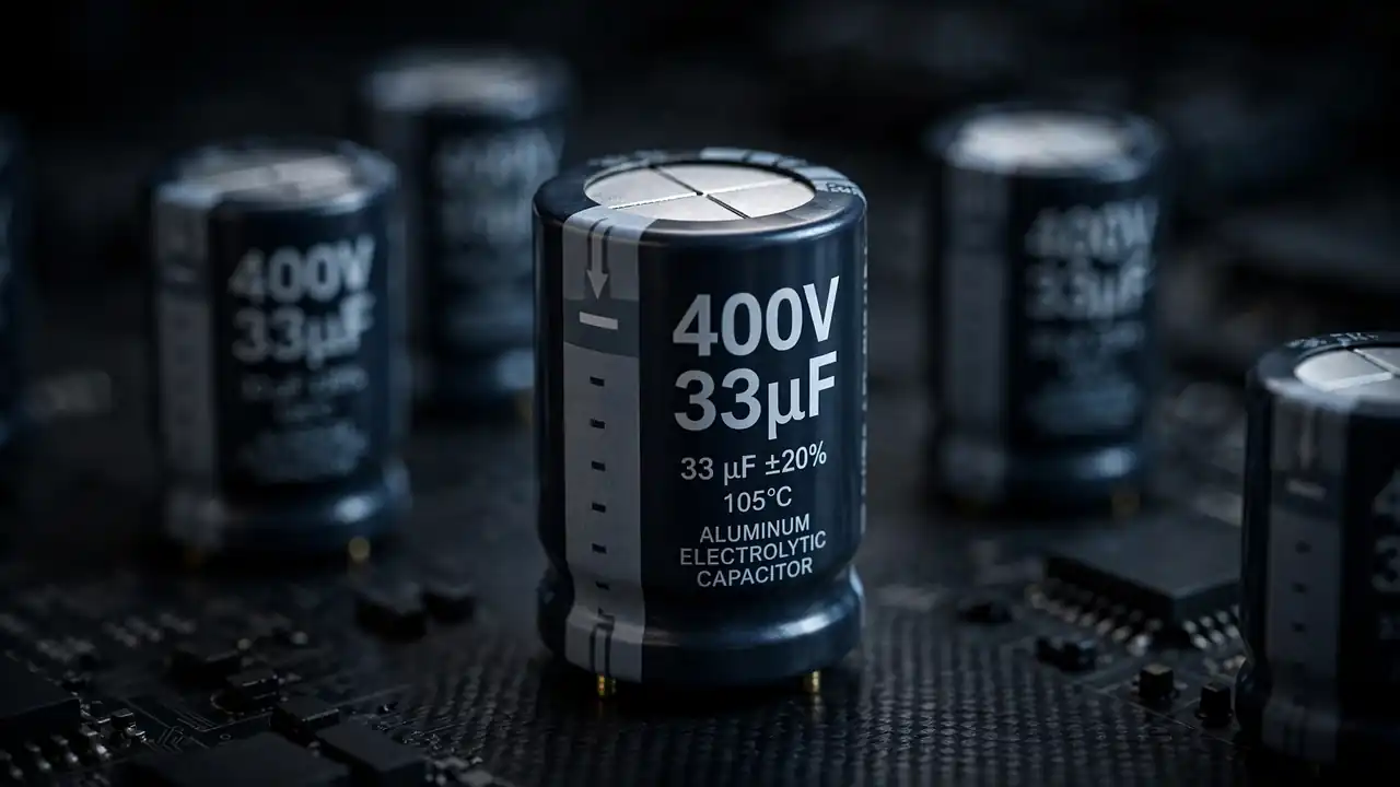
A dried-out 400V 33uF startup capacitor can leave an inverter dead with no standby light and no sign of life. The control chip never wakes, because it never gets its first charge. This guide shows how to find that small part, test it safely, and replace it without creating a new fault.
Safety first. This is a high-voltage part, even though the can is small. Disconnect mains, solar, and battery. Discharge the capacitor through a resistor and confirm zero volts with your meter before you touch it. A small can can still hold a charge that hurts, and a short with a screwdriver can damage the part and the tool.
What does 400V 33uF mean?
The markings are short, and each one matters. 33uF is the capacitance, a modest value for a high-voltage electrolytic. It is not bulk storage. Bulk storage belongs to the large cans in the hundreds of microfarads. A 33uF part serves filtering, timing, or startup jobs where moderate stored energy in a compact size is enough.
400V is the highest DC voltage rating. Never fit a lower rating, and never run the part above it. A common workshop margin keeps steady working voltage about 20 percent below the rating, which points to around 320V for a 400V part. That is a habit for longer life, not a spec printed on the sleeve. Check the series datasheet for the part in your hand.
It is a polarized aluminum electrolytic part, so the stripe marks the negative side. Tolerance is commonly plus or minus 20 percent, so a new 33uF part can read from about 26.4uF to 39.6uF and still sit inside its marked range. Temperature rating should be 105°C for power electronics. A small can heats fast when ripple current is high, so temperature margin is not optional here.
Because the can is small, its print can be tiny. Use a magnifier or your phone camera zoom to read it. Misreading 33uF as 330uF, or the reverse, is an easy mistake with costly results, because a 330uF part in a 33uF spot changes circuit behaviour in a big way.
Where does a 33uF capacitor hide?
Its most common home is the startup circuit. Many switch-mode controllers need a small high-voltage reservoir to begin switching. The 33uF charges through a startup resistor, the controller wakes, and then the auxiliary winding takes over. If the capacitor has dried out, the controller never gets its wake-up charge. The unit looks dead, which sends technicians toward fuses and power transistors while the real fault sits quietly nearby.
It also appears in high-voltage filtering in compact supplies, where board space forbids a larger can but the rail still needs smoothing. In snubber networks across switching transistors, it absorbs turn-off spikes, and there low ESR and good high-frequency behaviour matter more than bulk size. In voltage multiplier or charge pump stages, it can serve as a stage capacitor, where its value affects output impedance. A wildly different value there changes performance.
To find it on an unfamiliar board, look near the switch-mode controller chip or near the startup resistor, which is often a large high-value resistor from the high-voltage rail. The startup capacitor is often the small electrolytic closest to the controller supply pin. A schematic, if you can get one, makes this search trivial.
What symptoms point at an inverter dead with no standby light?
An inverter dead with no standby light is the headline symptom. When the startup capacitor fails, the controller never wakes, so nothing lights up. The second symptom is ticking at power-on. The controller charges the weak capacitor, tries to start, runs out of charge, shuts down, and tries again. That repeat cycle makes an audible tick from the transformer.
A third symptom is operation that fails after warm-up. Heat speeds electrolyte drying, so a capacitor that works cold and fails warm points straight at ageing. Visual cues still condemn a part at once: even slight doming of the top, or residue at the rubber seal underneath, means replacement. On a small can, compare with a known-good part of the same size. The difference in top flatness is visible when you sight along the top from the side.
How do you test it in five minutes?
For an inverter dead with no standby light, discharge through a resistor and confirm zero volts. Then follow these steps:
- Inspect under good light, with magnification if needed. Look for a flat top, a clean seal, and legible markings.
- Measure capacitance out of circuit, or with at least one lead lifted. Expect about 26.4uF to 39.6uF. Below 26.4uF shows real drying. Near zero with a persistent low resistance reading points to an internal short.
- Watch the resistance mode. The reading should climb toward infinity as the part charges from the meter. A 33uF part charges in a second or two, so watch closely.
- If you have an ESR meter, compare with the series datasheet or a known-good sample. ESR rise is an early warning, even while capacitance still reads inside range.
- 5. As a shortcut for startup diagnosis in an inverter dead with no standby light, you can measure across the part in circuit after discharge. If it reads far below 26.4uF even with parallel paths, it is bad. But a normal in-circuit reading proves nothing, because parallel parts can mask a dead capacitor. When in doubt, lift one lead.
| Test | Good result | Replace the part |
|---|---|---|
| Visual check | Flat top, clean seal, sharp print | Dome, residue, or swollen seal |
| Capacitance | About 26.4uF to 39.6uF | Below 26.4uF, or near zero |
| Resistance sweep | Reading climbs toward infinity in a second or two | Stuck low, or no climb |
| In-circuit capacitance | Far below range still means bad | Normal reading proves nothing; lift one lead to confirm |
How do you replace it the right way?
Isolate every power source and confirm zero volts. Photograph the original orientation before you desolder it. Match the specs: voltage 400V or higher, capacitance 33uF, temperature 105°C, and a can diameter that fits the pad spacing. In general filtering jobs, 22uF to 47uF can be tolerated. In startup jobs, stay close to 33uF, because the value sets the startup timing with its resistor.
Polarity needs care on a small part. The stripe can be hard to see, so confirm it under magnification before you solder. Check against your photo and the board marking. Soldering needs enough heat for a sound joint, but small pads need less heat than large bus capacitors. A cold joint on a startup capacitor creates an intermittent fault that is worse than the original problem.
After fitting, power up the inverter dead with no standby light and watch the start. Look for a crisp start with no ticking, no hesitation, and no repeated attempts. Then run the unit under load and confirm steady operation. If ticking returns, check the startup resistor and the controller supply path before you fit another capacitor.
Why does matching the original value matter so much here?
In a switch-mode supply, every capacitor takes part in control loop stability, the feedback maths that keeps output voltage steady. Change a small capacitor’s value or ESR by a large amount, and the loop can wobble. That is the deeper reason to match the original in startup and timing spots. You are not just swapping a part. You are keeping a tuned circuit tuned. The designer picked 33uF against a specific startup resistor, a specific controller, and a specific transformer.
The same care applies to upgrades. A larger capacitance in a startup circuit slows the startup ramp. A much lower ESR than the original can, in rare cases, affect loop stability in older designs that relied on some ESR for damping. When the original design is unknown, the safest repair is the closest match: same value, same voltage, same temperature grade, and a reputable series.
If you service the same inverter models often, keep notes on which small capacitors fail and at what age. Patterns emerge. A model that always loses its startup capacitor at year four tells you to change it preventively at year three during any other service. That model-specific knowledge is what turns a good technician into the one people call first.
Frequently Asked Questions
Can I use 47uF instead of 33uF? In general filtering spots, usually yes. In startup spots of an inverter dead with no standby light, the change shifts startup timing, so it may still work, but match the original when you can. Never go below the original value in a startup job.
Why does the unit tick but not start? That is the classic hiccup in an inverter dead with no standby light. The controller charges the startup capacitor, tries to start, runs out of charge, shuts down, and repeats. Replacing the startup capacitor usually stops the ticking.
Is 400V enough, or should I use 450V? If the circuit was designed for 400V with proper margin, 400V is correct. A 450V replacement is always acceptable on voltage grounds, as long as it fits. Never go below the original rating.
Can heat alone kill this capacitor without electrical stress? Yes. Electrolyte dries faster at high temperature, even with no electrical load. In an inverter dead with no standby light, a 33uF part next to a hot heat sink in a poorly ventilated inverter ages fast. Placement and airflow matter as much as electrical ratings.
How do I find this capacitor on an unfamiliar board? Look near the controller chip or the startup resistor from the high-voltage rail. The startup capacitor is often the small electrolytic closest to the controller supply pin. A schematic makes it easy.
Should I replace it preventively during other repairs? If the board is already open and the unit is several years old, replacing the small startup electrolytics is cheap insurance. They are among the most age-sensitive parts on the board.
Next step
An inverter dead with no standby light deserves a startup capacitor test before a board swap. For the next value up, read the 400V 47uF capacitor guide, and for the larger filtering value, see the 400V 82uF capacitor guide. When you order, ask for the exact voltage, capacitance, temperature rating, and series, and test the new part before you fit it.
Related Technical Guides
 Category:
General
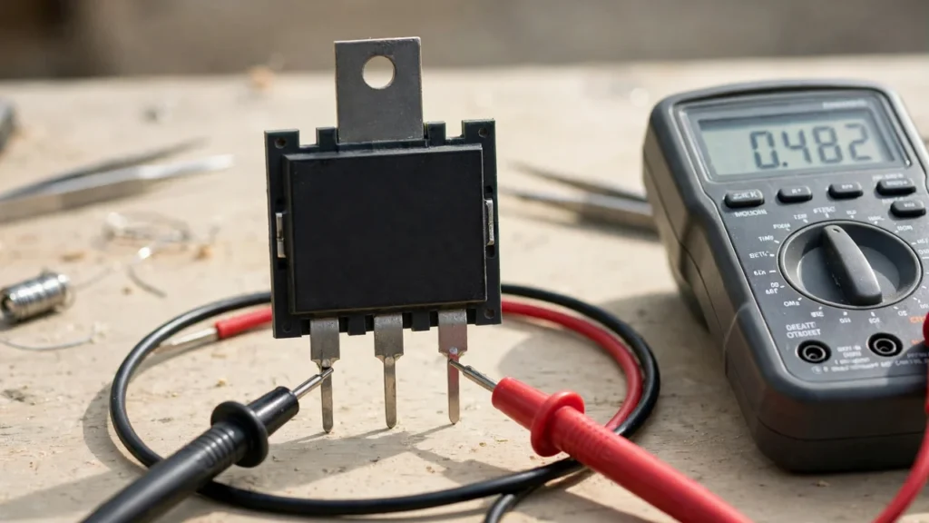
How to Test a MOSFET With a Multimeter 2026: Find a Bad MOSFET Before It Burns Your Board
Last month, a technician brought me a dead inverter board. He had already fitted a new MOSFET. The board died again in…
 Category:
General
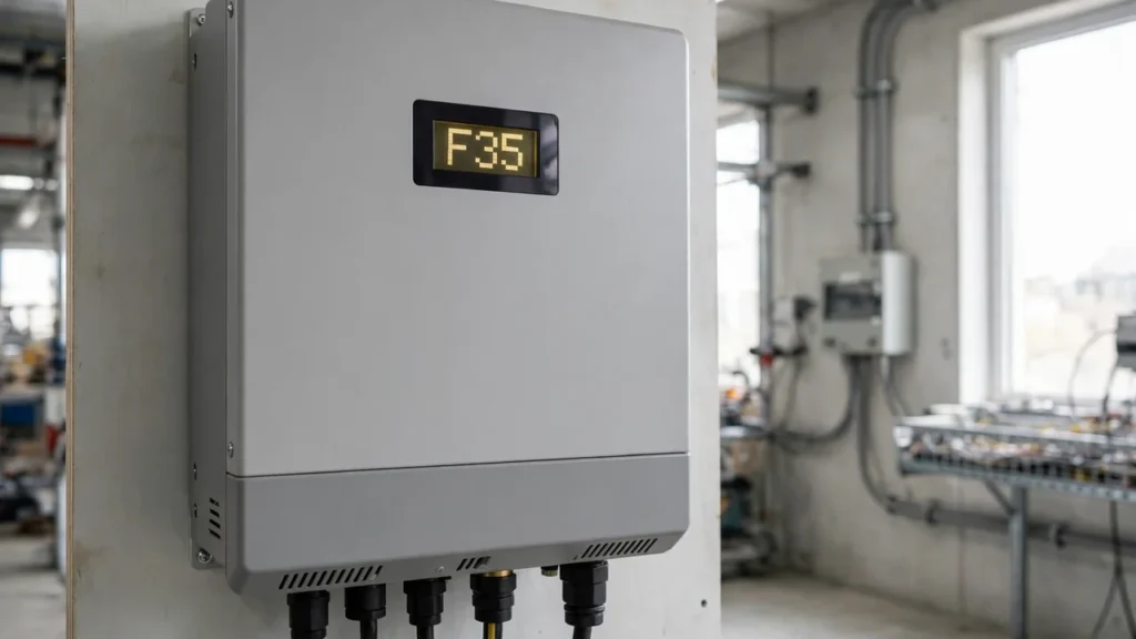
Inverex Nitrox Fault Codes 2026: Technician’s Complete Decode List for F01 to F64
Inverex Nitrox Fault Codes 2026: Technician’s Complete Decode List for F01 to F64 One evening, a shop owner called me. His Inverex…
 Category:
Electronic Parts
Where to Buy Inverter Repair Parts in Peshawar
Looking for inverter repair parts in Peshawar? Learn what inverter spare parts are important and where to buy original inverter repair parts…
1 Comment
[…] auxiliary capacitors before you replace expensive boards. For the smaller startup value, read the 400V 33uF capacitor guide, and for the larger filtering value, see the 400V 82uF capacitor guide. When you order, ask for the […]