
Rectifier Diode and Bridge Rectifier Fault 2026: Test It With a Multimeter Like a Technician
Published on 18 November 2026. Updated on 18 November 2026. A rectifier diode and bridge rectifier fault is easy to spot: a bridge rectifier shows about 0.4 to 0.8 volts in one…

Published on 18 November 2026. Updated on 18 November 2026.
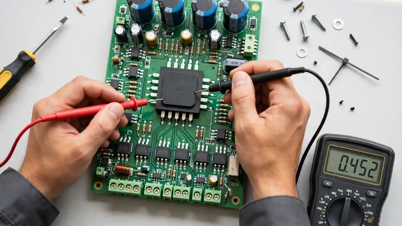
A rectifier diode and bridge rectifier fault is easy to spot: a bridge rectifier shows about 0.4 to 0.8 volts in one direction and OL in the other direction on a multimeter in diode mode. If it shows near zero both ways, it is shorted. If it shows OL both ways, it is open. That bridge must be replaced at once.
In This Guide
Last month, a customer brought his dead inverter to our repair centre: it had blown two fuses in one week, and he was sure the whole inverter was finished. Our technician opened it, tested the small black square part near the input fuse, and found one shorted diode inside it. He changed that one part, and the inverter worked again the same day.
That small black square is the bridge rectifier, one of the first parts to fail when an inverter dies or keeps blowing fuses. The good news is that you can test it with a cheap multimeter in a few minutes. By the end, you will know what each reading means and when the bridge must be replaced.
Trust nudge: This guide comes from SunTech Mall, a solar inverter spare parts store in Pakistan whose repair team tests and fixes inverters and UPS systems every day.
What Does a Rectifier Diode and a Bridge Rectifier Do in an Inverter? — the job of the bridge What Are the Signs of a Bad Rectifier Diode or Bridge Rectifier? — the warning signs What Does Each Multimeter Reading Mean? — the reading table How Do I Test a Bridge Rectifier With a Multimeter? — six steps How Do I Test a Single Rectifier Diode With a Multimeter? — the one-diode test What Should I Check Before I Blame the Bridge Rectifier? — other suspects first How Do I Choose the Right Replacement Bridge Rectifier? — match the part When Should I Replace the Bridge Instead of Repairing the Board? — repair or replace? When Should I Ask a Technician? — know when to stop
What Does a Rectifier Diode and a Bridge Rectifier Do in an Inverter?
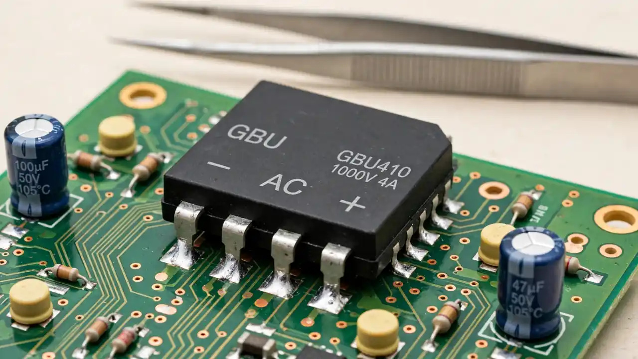
A diode is a one-way gate for electric current: it lets current flow in one direction and blocks it in the other. That one simple job turns AC power into DC power, which an inverter needs to charge its capacitors and run its circuits.
A bridge rectifier is four diodes joined in one small package. It has four pins: two AC inputs marked (~), one positive DC output (+), and one negative DC output (−). The four diodes work as a team, so both halves of the AC wave come out as DC: a full-wave bridge.
In a solar inverter or UPS, the bridge sits at the very start of the power path, just after the input fuse and just before the big capacitors. Power comes in, the bridge turns it into DC, and the capacitors smooth it for the rest of the board. If the bridge fails, the inverter acts dead.
Think of the bridge as a one-way roundabout: if one gate breaks open, the fuse blows, and if one gate jams shut, only half the power gets through.
Note: A bridge is a small part, but it carries the full input current. A bridge with too low a current rating will run hot and fail again, so the replacement must match or beat the old part.
What Are the Signs of a Bad Rectifier Diode or Bridge Rectifier?
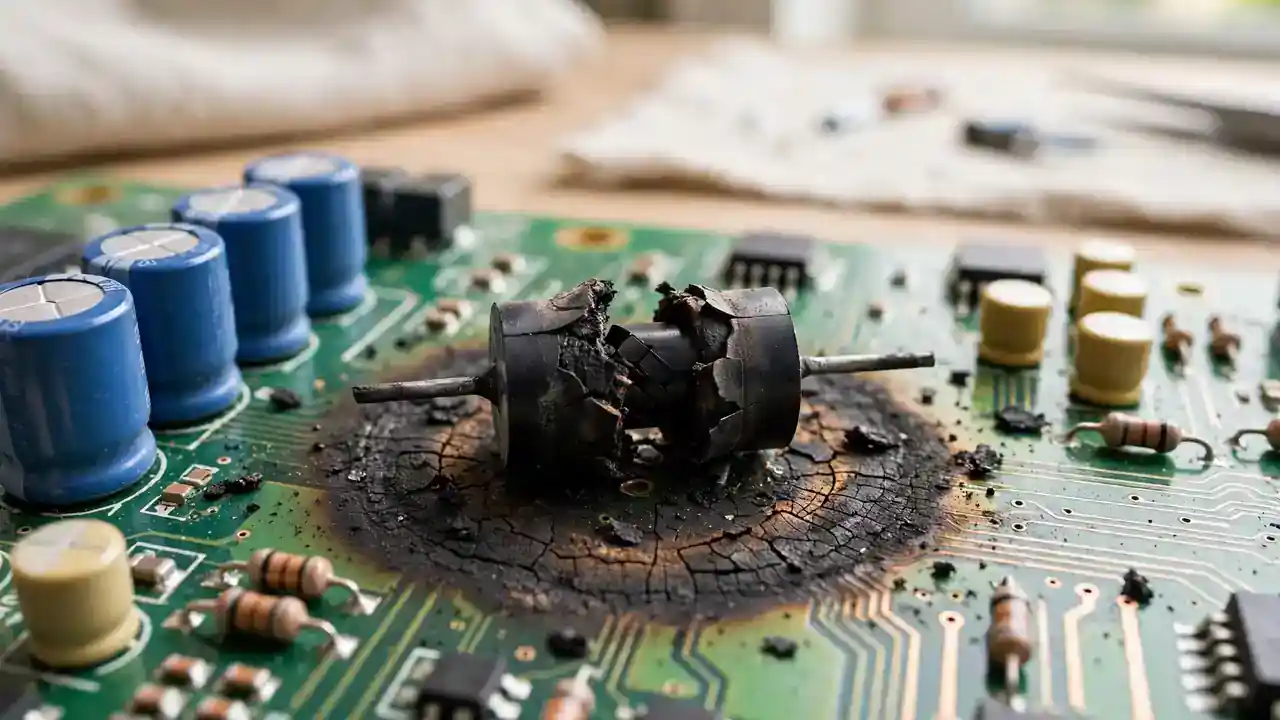
A bad bridge gives clear signs before you ever open the case. The first sign is an inverter that is fully dead: no lights, no display, no fan, nothing at all. The second sign is a fuse that blows the moment power is switched on, even a new fuse: a shorted diode acts like a wire across the input.
The third sign is a humming or buzzing sound with weak or no output: one open diode means only half the AC wave reaches the capacitors. The fourth sign is no DC output at all, even though the fuse is fine and input voltage is present. The fifth sign is a burnt smell near the input stage, or a bridge that looks cracked or blackened.
Look for heat too. A bridge far hotter than the parts around it, or a dark burn ring around its pins, has been running too hot. Repeated surges and heavy inrush current at every start age the bridge, until one day it fails short.
If your inverter does not turn on at all, read our guide on why a solar inverter does not turn on first: a loose battery cable or a blown fuse is the most common cause. If the fuse is fine and the inverter is still dead, the bridge is one of the first parts a technician tests.
Bonus Tip: Before you open the inverter, smell the air vents. A sharp burnt smell near the input side points at the bridge or the fuse area, while a sweet smell points at a swollen capacitor. Your nose can tell you which part to test first.
What Does Each Multimeter Reading Mean?
The table below is the heart of this guide. Set your multimeter to diode mode (the diode symbol), then test each of the four diodes inside the bridge. A healthy silicon diode shows about 0.4 to 0.8 volts in one direction and OL in the other direction. OL means open loop: the meter sees no path, which is what a good diode does in reverse.
| Reading | What it means | What to do |
|---|---|---|
| About 0.4 to 0.8 volts one way, OL the other way | Healthy diode, current flows one way only | The diode is good; test the next one |
| Near 0 volts (or a beep) both ways | Shorted diode, the junction has become a wire | Replace the bridge |
| OL both ways | Open diode, the junction no longer conducts | Replace the bridge |
| Same low reading both ways | Shorted arm of the bridge | Replace the bridge |
| About double the single drop across the + and − pins | Two diodes in series, which is normal on that path | Good on that path; test the other pairs |
| Reading jumps around each time | Weak or heat-damaged diode that fails under load | Replace the bridge; do not trust an unsteady reading |
Two rows need a plain warning. A shorted diode blows the fuse the moment power is switched on, and a bigger fuse will let the short burn the board instead. Never fit a bigger fuse. And a jumping reading is easy to miss: the diode can pass a cold test and still fail when it gets hot.
Note: A diode-mode test proves that a junction exists and points the right way. It does not prove that the bridge will survive its full job under load.
How Do I Test a Bridge Rectifier With a Multimeter?
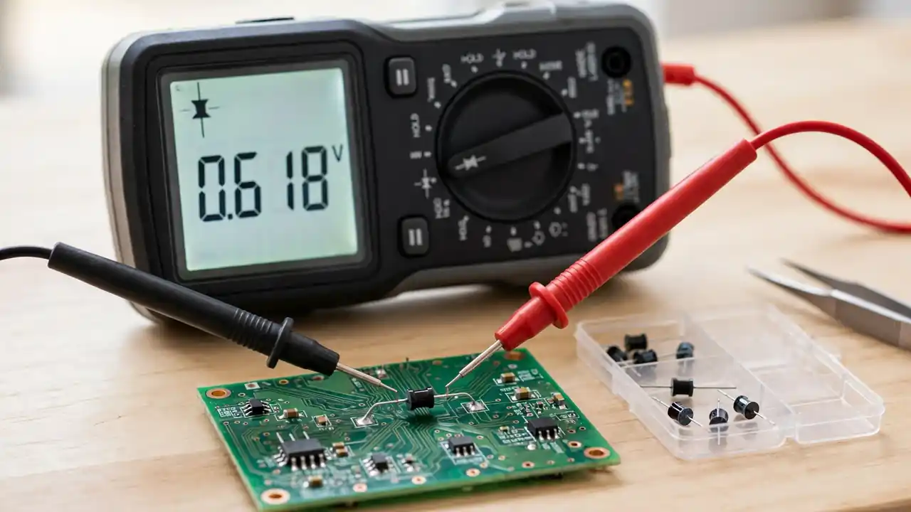
Test the bridge out of the circuit for the surest result: a part still soldered on the board can give false readings. If you cannot remove it, the in-circuit test is still a useful first check, but a bad reading in circuit must be confirmed out of circuit.
- Switch everything off and make it safe. Disconnect the battery, the solar panels, and the grid supply. Wait a few minutes for the big capacitors to discharge, then check that no voltage is left. Never test a live board.
- Set the multimeter to diode mode. The meter pushes a tiny current through the diode and shows the voltage drop.
- Find the four pins. The two AC pins are marked with a wavy line (~), the positive pin with (+), and the negative pin with (−), printed on the top of the black package.
- Test each diode one by one. Red probe on an AC pin, black probe on the (+) pin: about 0.4 to 0.8 volts. Swap the probes: OL. Do the same for the second AC pin, then from the (−) pin to each AC pin. All four diodes must show a drop one way and OL the other way.
- Test the + to − path. Put the probes across the (+) and (−) pins: about double a single drop, because the path crosses two diodes. A reading far below double means a shorted junction in the loop.
- Judge the bridge by its worst diode. If any one of the four diodes is shorted or open, the whole bridge is faulty. Replace the full package, and test the new part before you solder it in.
If you have tested MOSFETs before, the habit is the same: one part, one direction at a time. Our guide on how to test a MOSFET with a multimeter shows the same diode-mode method on a power transistor.
How Do I Test a Single Rectifier Diode With a Multimeter?
A single rectifier diode, such as the common 1N4007 1000V 1A general purpose diode, is even easier to test than a bridge: it has only two legs. The leg with the stripe is the cathode, and the other leg is the anode. Put the red probe on the anode and the black probe on the cathode, and a healthy silicon diode shows about 0.5 to 0.8 volts.
Swap the probes, red on the cathode and black on the anode, and the meter must show OL. That is the whole test: one direction conducts, the other blocks. Near zero both ways means shorted; OL both ways means open. A Schottky diode is different: its forward drop is lower, about 0.2 to 0.4 volts, so check its datasheet if the reading looks low but it still blocks in reverse.
Single diodes fail the same way a bridge fails: a surge breaks the junction short and the fuse blows, or heat cracks the body and the diode goes open. In a small charger, one shorted diode can stop the whole unit. Test out of circuit when you can: a diode still soldered on the board can read through a part next to it and fool you.
What Should I Check Before I Blame the Bridge Rectifier?
A dead inverter is not always a dead bridge, so check the cheap suspects first. Start with the input fuse, the most common cause of a dead inverter: a good fuse beeps on continuity mode, a blown fuse shows OL. Then check the battery cables: a loose or burnt joint drops the voltage before it reaches the bridge.
Next, look at the big capacitors after the bridge. A swollen or leaking capacitor can sag the DC output and make the inverter hum, exactly like an open bridge diode. Our guide on inverter capacitor bulging signs shows what a dying capacitor looks like, and the capacitors section lists board capacitors by size.
Then think about the power stage after the bridge. A shorted MOSFET or a shorted IGBT can also blow the input fuse the moment power is switched on, so a blown fuse alone does not prove the bridge is bad. Test the bridge first, then the power transistors if the bridge is good. A burnt gate driver IC can look like a dead power stage too, and our guide on gate driver IC failure signs explains how one burnt driver can fool you.
Note: Never work on a live inverter. Disconnect the battery, the solar panels, and the grid supply before you touch anything, and wait a few minutes for the capacitors to discharge. Board work must be done by a qualified technician only: a capacitor can hold a dangerous charge even after the inverter is switched off. If any step feels unsafe, stop and call a technician.
How Do I Choose the Right Replacement Bridge Rectifier?
Match the old part, never guess. The two numbers that matter are the voltage rating and the current rating, printed on the package or written in the manual. The voltage rating is the highest reverse voltage the bridge can block, and the current rating is the highest average current it can carry with proper cooling. A replacement must match or beat both numbers, or it will fail again in a few weeks.
The package matters too. A GBU bridge mounts flat on the board with four legs in a row, while a small SMD bridge solders flat on the surface, and the two do not swap. Read the part number off the old bridge before you order, and check the manual if the markings are burnt away.
For most home inverters, the GBU08 1000V 8A bridge rectifier is a common fit: 1000 volts and 8 amps in the GBU package, with proper cooling assumed for the full rating. For small charger boards, the DB107 1000V 1A SMD bridge rectifier fits where a tiny surface-mount bridge is needed. The diodes section lists bridges and single diodes together, so you can match package and rating side by side. Always check the live price on the website, and test the new bridge before you solder it in.
When Should I Replace the Bridge Instead of Repairing the Board?
Replace the bridge when the test says it is shorted or open and the rest of the board looks healthy. A bridge is a cheap part and a quick job: desolder four pins, fit the new part, test it, and run the inverter on a test load. That is almost always worth doing, even on an old inverter.
Repair further only when the bridge is good and the fault is somewhere else. If a shorted MOSFET or a dead driver kept overloading the bridge, changing the bridge alone will just blow the new one too. Test the parts around the bridge first, and run the inverter on a test load before handing it back.
Replace the whole inverter only when the board is burnt in several places at once, or the same fault keeps coming back, or the repair bill comes close to the price of a new inverter. Our guide on how many kW inverter for home shows how to count your real load first, and our solar inverter repair cost guide gives honest estimate ranges for each common fault, so you can tell a fair bill from an unfair one.
When Should I Ask a Technician?
Most of this guide you can use yourself: read the signs, test the bridge, and match the replacement part number. But some jobs belong to a technician: any work inside the inverter, any board repair, and any fault that comes back twice. A fault that comes back twice is never bad luck: the real cause was never found, and only a bench test will find it.
Ask a technician when you smell burning, see a black mark on the board, or the fuse blows the moment power is switched on: these are signs of a short inside the inverter. Do not keep switching it on, and do not fit a bigger fuse. Switch it off, disconnect it, and take it to a technician.
SunTech Mall runs its own inverter and UPS repair service centre in Pakistan. Bring your inverter there, or buy the parts and get your own technician to fit them. Bring the inverter model, the fuse size, and your multimeter readings, and the technician can confirm the fault in minutes.
Frequently Asked Questions
How do I test a bridge rectifier with a multimeter?
Set the multimeter to diode mode, then test each of the four diodes: red probe on an AC pin, black probe on the (+) pin should show about 0.4 to 0.8 volts; swapped probes should show OL. Repeat for the second AC pin and for the (−) pin to each AC pin. Any shorted or open diode means the whole bridge must be replaced.
What is a good reading for a bridge rectifier?
A good bridge shows about 0.4 to 0.8 volts forward and OL in reverse on every one of its four diodes. Across the (+) and (−) pins it shows about double a single drop, because that path crosses two diodes. A steady reading on all four is the pass mark.
Can a bad bridge rectifier blow a fuse?
Yes. A shorted diode inside the bridge acts like a wire across the input, so the fuse blows the moment power is switched on. Never fit a bigger fuse: the short will burn the board instead. Replace the shorted bridge, then fit a fuse of the same size.
What happens when one diode in a bridge rectifier fails open?
One open diode means only half the AC wave reaches the capacitors, so the DC output sags and ripples. The inverter may hum, run weak, or shut down under load. The bridge still needs replacing as one part: three good diodes and one open diode cannot give clean DC.
How do I know if my bridge rectifier is shorted or open?
A shorted bridge shows near zero volts or a beep in both directions on the affected pin pair. An open bridge shows OL in both directions. A healthy bridge shows a drop one way and OL the other way. Test all four diodes: the worst reading decides.
Can I test a bridge rectifier without removing it from the board?
You can do a first check in circuit, but the reading can be false because other parts share the same paths. A part that looks bad in circuit must be tested out of circuit before you call it dead.
Final Thoughts
A bridge rectifier is a small part with a big job, and a multimeter tells you its health in a few minutes. Find your reading in the table, and trust what the meter says: a drop one way and OL the other way means good, anything else means replace.
So my request is this. Before you buy a new inverter or pay for a big repair, test the bridge first: the first part in the power path, the cheapest common cause of a dead inverter, and the easiest fault to prove.
Ready to check your part? The diodes section at SunTech Mall lists bridge rectifiers and diodes for these repairs — check the live price on the website. Questions? Message SunTech Mall on WhatsApp at 0306-2244820 with your inverter model and readings, and we will help you match the right part.
Published on 18 November 2026. Updated on 18 November 2026.
Sources: JLCPCB — How to Test a Diode With a Multimeter (forward 0.5–0.8V, OL reverse) ; ElectroUniversity — How to Test Bridge Rectifier With Multimeter (0.5–0.8V forward, OL reverse) ; Electric Shocks — How to Test a Bridge Rectifier (0.4–0.8V forward; in-circuit test is preliminary) ; Good-Ark — Bridge Rectifier Testing: Seven Terminal Checks (double drop across + and −)
Related Technical Guides
 Category:
General
SPD and Voltage Protection 2026: Save Your Solar Inverter From Power Surges
An SPD, or surge protection device, guards your solar inverter from voltage spikes caused by lightning and grid switching. It sends the…
 Category:
General
Day Solar Inverter Repair 2026: 7 Common Faults and the Real Parts That Fix Them
A Day Solar inverter fails in seven common ways: no output, repeated restarts, heat shutdown, no solar input, blown fuses, strange noise,…
 Category:
General
Lithium Battery Lifespan 2026: 7 Mistakes That Kill Your Battery Early — A Technician’s Guide
Published on 20 November 2026. Updated on 20 November 2026. A lithium battery lasts years longer when you avoid seven mistakes: draining…
2 Comments
[…] Rectifier Diode and Bridge Rectifier Fault 2026: Test It With a Multimeter Like a TechnicianNovember… […]
[…] storm, and the power parts are burnt. A surge can also kill the rectifier stage, and our guide on rectifier diode and bridge fault explains those symptoms in simple words. A small SPD on the wall would have taken that hit for a […]