

SG3525 vs UC3845 PWM IC 2026: Which One Runs Your Inverter (and How to Pick the Right One)
Published on 14 November 2026. Updated on 14 November 2026. SG3525 is a voltage-mode PWM controller, and UC3845 is a current-mode PWM controller. They are not interchangeable. SG3525 suits push-pull and bridge…

Published on 14 November 2026. Updated on 14 November 2026.
SG3525 is a voltage-mode PWM controller, and UC3845 is a current-mode PWM controller. They are not interchangeable. SG3525 suits push-pull and bridge power stages with two outputs, while UC3845 suits flyback and boost supplies with one output. Match the part number, package, and pins on your board before you order.
In This Guide
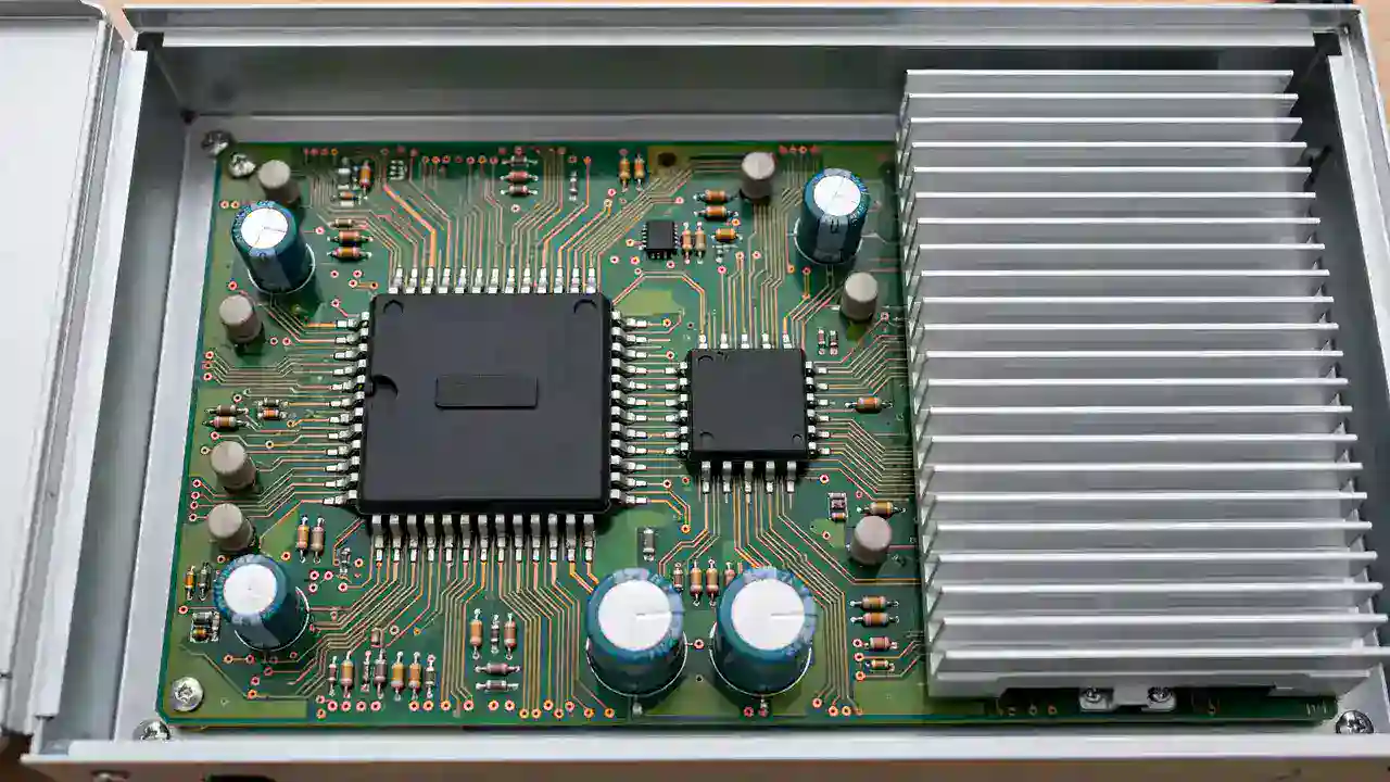
Last month, a technician brought a dead inverter board to our repair centre. He had fitted a new PWM chip, and the board died again in ten minutes. He was sure the new chip was fake. It was not fake: he had fitted an SG3525 where the board needed a UC3845. The two chips look alike at a glance, but inside they work in different ways, and the wrong one cannot do the right job.
This story is common in repair shops across Pakistan. A small control chip decides how the whole power stage switches. Fit the wrong one, and the inverter stays dead, or the new chip dies at once. This guide stops that mistake: what each chip does, how they differ, and how to match the right replacement.
Trust nudge: This guide comes from SunTech Mall, a solar inverter spare parts store in Pakistan that also repairs inverters and UPS systems every day. The checks below are the same ones our repair team uses on the bench.
What Is a PWM IC, and What Does It Do Inside an Inverter? — the small boss that sets the switching rhythm What Is the SG3525, and Where Does It Work? — the two-output voltage-mode controller What Is the UC3845, and Where Does It Work? — the single-output current-mode controller SG3525 vs UC3845: What Is the Real Difference? — the side-by-side table How Do I Find Which PWM IC My Board Uses? — 6 steps before you order Can I Use an SG3525 Instead of a UC3845 (or the Other Way Round)? — the swap question What Goes Wrong When the Wrong PWM IC Is Fitted? — the damage a wrong fit causes How Do I Match the Right Replacement PWM IC? — part number, package, and pins When Should I Take the Board to a Repair Shop? — know when to stop
What Is a PWM IC, and What Does It Do Inside an Inverter?
A PWM IC is a small chip that controls how fast the power switches inside your inverter turn on and off. PWM stands for pulse width modulation: the chip sends out a fast train of on-off pulses, and it changes how wide each pulse is to control the power.
Think of it like a tap that opens and closes very fast. When the tap stays open longer each time, more water flows. The PWM chip is the hand on that tap: it widens or narrows the pulses to keep the output steady.
Inside an inverter, the PWM chip does not carry the big power itself. It sends small control pulses to the gate driver and the big power switches, the MOSFETs and IGBTs. Those switches do the heavy work. If the PWM chip sends the wrong pulses, or no pulses at all, the inverter cannot make AC power. Our guide on why a solar inverter does not turn on walks through the outside checks first, before any board work begins.
One board can carry both chips at once, each doing its own job: the main stage turns battery DC into AC, while the small auxiliary supply makes the low voltages for the control board. Our guide on the chopper transformer in a hybrid solar inverter explains that small supply: it feeds the low voltages the whole control board needs to wake up.
What Is the SG3525, and Where Does It Work?
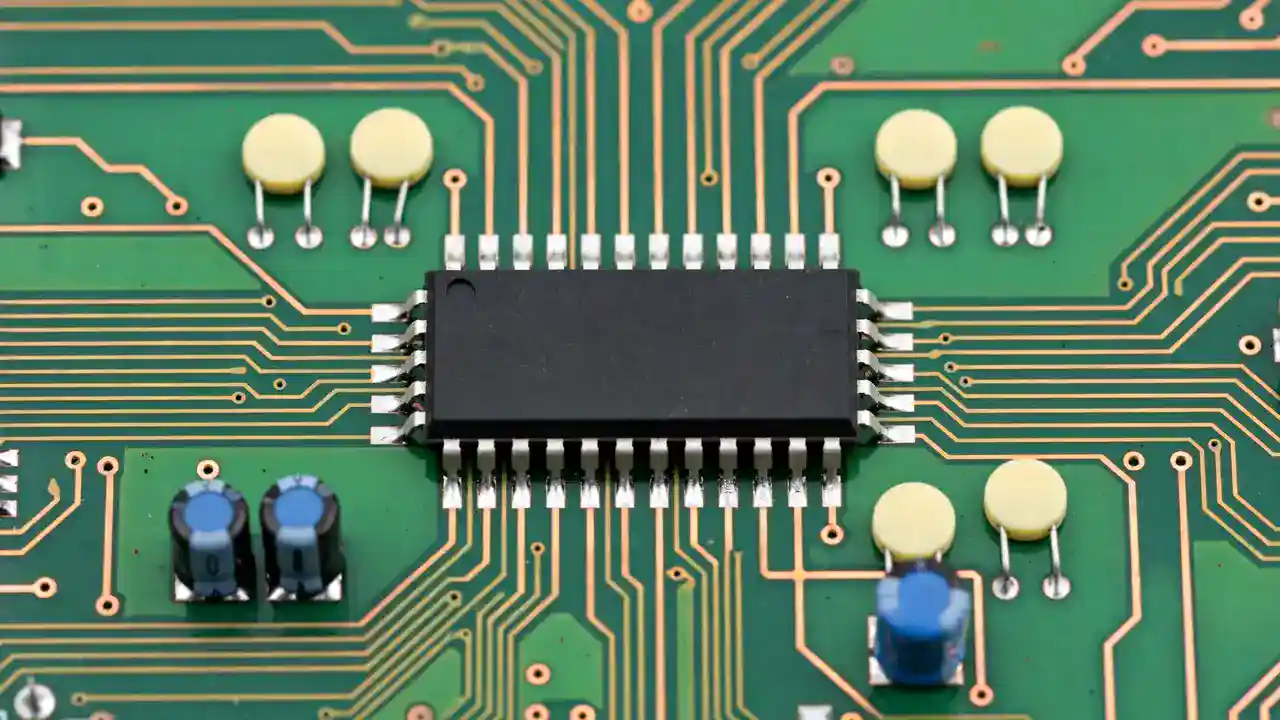
The SG3525 is a voltage-mode PWM controller: it watches the output voltage and changes the pulse width to hold that voltage steady. It does not watch the current through the switch on every cycle. It is a 16-pin chip, made in DIP-16 through-hole and SOIC-16 and SOP-16 surface-mount versions. Full numbers are in the SG3525A datasheet.
The SG3525 runs on a supply of 8 to 35 volts. Inside, it has a 5.1 volt reference, trimmed to within 1 percent. Its oscillator runs from 100 Hz to 400 kHz, and one maker's version reaches up to 500 kHz. It has two outputs, and each output can source or sink up to 400 mA peak. Each output can reach a maximum duty cycle of about 45 to 49 percent, because the two outputs take turns.
The chip also has a soft-start circuit, a shutdown pin, an under-voltage lockout, and a separate sync pin. The dead time between the two outputs is set by one resistor between the CT and Discharge pins. It uses latching PWM and pulse-by-pulse shutdown, so a fault can stop the pulses at once.
That makes the SG3525 a natural fit for push-pull, half-bridge, and full-bridge power stages. In a push-pull stage, two switches take turns, and the SG3525 has exactly two outputs for that job. SunTech Mall stocks the SG 3525(ON) PWM CONTROLLER IC DIP-16 for through-hole boards, and the SG 3525 PWM CONTROLLER IC NARROW SOP-16 for compact surface-mount boards. Check the live price on the product page before you order.
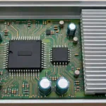
I have seen this chip on the bench many times: a 16-pin chip near the big MOSFETs and the main transformer, driving the main power stage.
Note: Never open a live inverter case. Capacitors inside hold charge even after the inverter is switched off and unplugged, so board work is a trained technician's job. Discharge the capacitors first, and only with the safe method your training teaches.
What Is the UC3845, and Where Does It Work?
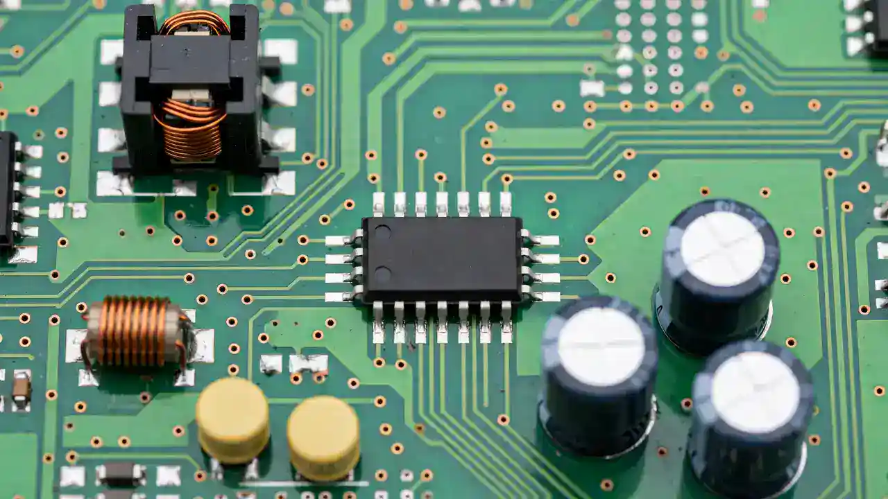
The UC3845 is a current-mode PWM controller: it watches the output voltage and the current through the switch on every single cycle. If the current jumps too high in one cycle, the chip can stop that pulse at once. Full numbers are on the TI UC3845A page and in the UC3845A datasheet.
The UC3845 is a small chip with only 8 pins, made in DIP-8 through-hole and SOIC-8 surface-mount versions. Inside, it has a 5.0 volt reference. Its under-voltage lockout turns the chip on at about 8.5 volts and off at about 7.6 volts. Its oscillator runs up to 500 kHz. It has one output, a totem-pole stage that can push up to 1 amp. Its maximum duty cycle is 50 percent, because an inside flip-flop blanks every other cycle. Its startup current is very low, under 0.5 mA, and a current-sense pin feeds the switch current back for that cycle-by-cycle limit.
The UC3845 belongs to a family of four, and the split is worth knowing. The UC3842 and UC3844 start at 16 volts on and 10 volts off, for off-line supplies. The UC3843 and UC3845 start at the lower 8.5 volt level, for low-voltage supplies. The UC3842 and UC3843 can reach about 100 percent duty cycle, while the UC3844 and UC3845 are capped at 50 percent. So the last digit matters.
With one output and a 50 percent duty cap, the UC3845 fits flyback and boost supplies. In an inverter, that usually means the small auxiliary supply: the chopper section that makes the 5 volt, 12 volt, and 15 volt rails for the control board. SunTech Mall stocks the UC3845BN CURRENT MODE PWM IC DIP-8 for through-hole boards, and the UC3845B SMD CURRENT MODE PWM IC SOT-8 for compact surface-mount boards. Check the live price on the product page before you order.
On the bench, I find this small 8-pin chip near the chopper transformer whenever a dead inverter has lost its control-board power.
Bonus Tip: Take a clear photo of the old chip before you remove it. Photograph the full part number, the package, and the pins around it. That one photo stops most wrong orders before they happen.
SG3525 vs UC3845: What Is the Real Difference?
The table below puts the two chips side by side. Every number comes from the datasheets linked in this guide.
| Feature | SG3525 | UC3845 |
|---|---|---|
| Control mode | Voltage-mode | Current-mode: watches voltage and current every cycle |
| Pins | 16 pins (DIP-16, SOIC-16, SOP-16) | 8 pins (DIP-8, SOIC-8, SOT-8) |
| Supply voltage | 8 to 35 V | Starts at 8.5 V, stops at 7.6 V (UVLO) |
| Reference voltage | 5.1 V, trimmed to plus or minus 1 percent | 5.0 V |
| Outputs | Two outputs, take turns | One output |
| Output current | 400 mA peak per output, source or sink | 1 A totem-pole output |
| Maximum duty cycle | 45 to 49 percent per output | 50 percent, set by an inside flip-flop |
| Oscillator range | 100 Hz to 400 kHz (500 kHz in one version) | Up to 500 kHz |
| Startup current | Normal supply current to start | Very low, under 0.5 mA |
| Current limit | Pulse-by-pulse shutdown | Cycle-by-cycle limit |
| Soft-start | Built in, one timing capacitor | Needs outside parts |
| Sync pin | Yes, a separate sync pin | No separate sync pin |
| Dead time | One resistor, CT to Discharge | Oscillator parts RT and CT |
| Typical inverter job | Main stage: push-pull, half-bridge, full-bridge | Auxiliary supply: flyback, boost |
Three rows decide almost every repair. First, the control mode: voltage-mode against current-mode. A voltage-mode chip only watches the output voltage. A current-mode chip also watches the switch current. Second, the outputs: two against one. A push-pull stage needs two outputs that take turns, and only the SG3525 has them. Third, the pins: 16 against 8.
The duty cycle rows look close, and that fools people. Both chips stop near 50 percent, but for different reasons. The SG3525 stops near 49 percent per output because its two outputs must take turns. The UC3845 stops at 50 percent because its inside flip-flop blanks every other cycle on purpose.
How Do I Find Which PWM IC My Board Uses?
Work through these six steps before you order any chip. Together they stop the most common wrong order in PWM repair.
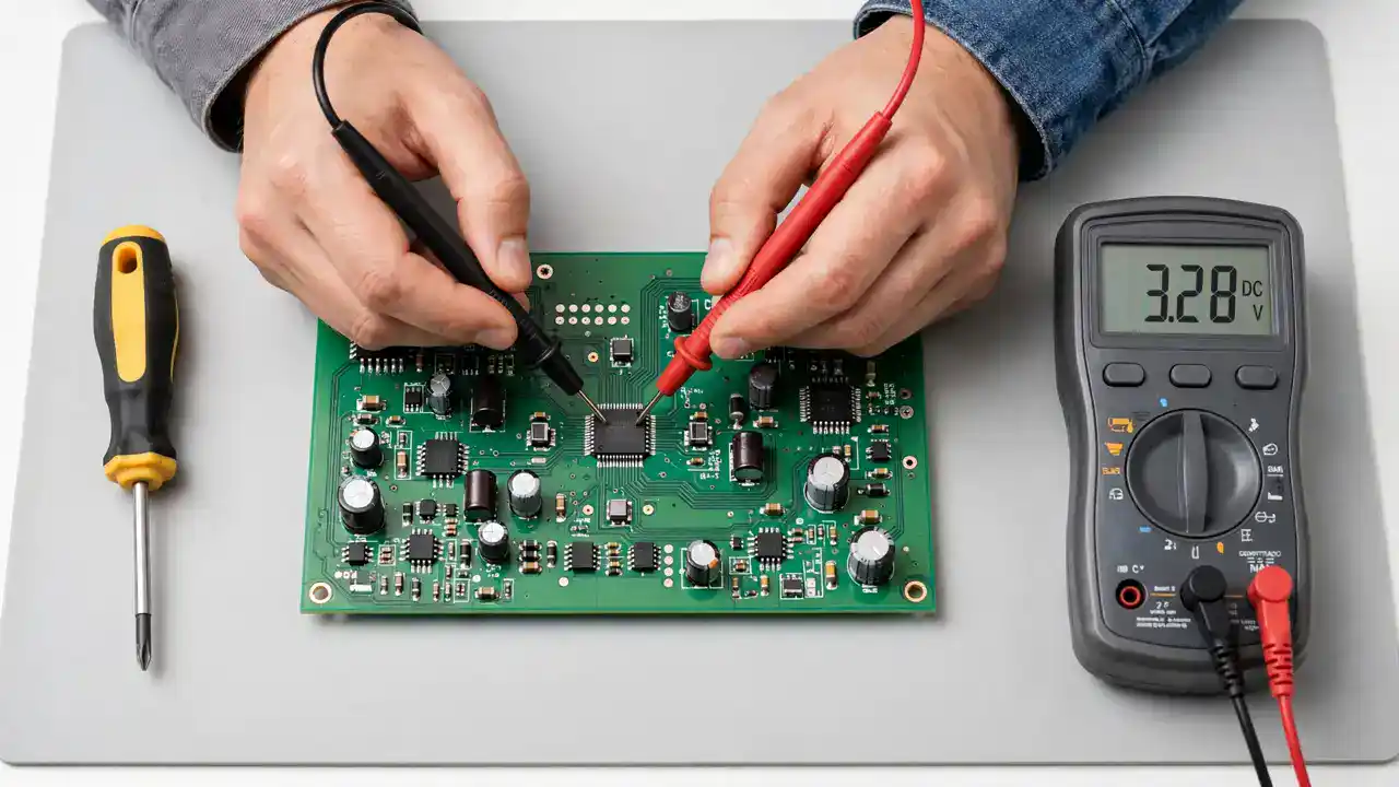
- Switch everything off and make the board safe. Unplug the inverter, take the battery leads off, and take the solar input off. Wait, because the big capacitors inside hold charge after power-off. Board work is a trained technician's job.
- Find the PWM chip on the board. A chip near the big MOSFETs and the main transformer is usually the main-stage controller. A small chip near the chopper transformer is usually the auxiliary supply controller.
- Read the full part number on the chip body. It must read SG3525 or UC3845 in full. On the UC3845 family, the last digit matters: UC3842, UC3843, UC3844, and UC3845 are different parts. If the number is burnt off, do not guess. Take the inverter model and a board photo to a technician.
- Count the pins and name the package. Sixteen pins means a 16-pin chip like the SG3525. Eight pins means an 8-pin chip like the UC3845. Legs through holes mean DIP; legs flat on the surface mean SOIC, SOP, or SOT.
- Check the circuit around the chip. Two outputs going to two MOSFET groups point to the SG3525. One output going to a single switch, with a small resistor feeding back to a sense pin, points to the UC3845. A flyback transformer points to the UC3845, and a centre-tapped transformer with two switches points to the SG3525.
- Confirm with the datasheet before you order. Check the pin order, the supply range, and the package drawing against your board, then order the exact match from a supplier who sells original parts.
If any step gives a different answer from the others, stop and ask a technician. A guess will cost a chip, and maybe a board.
Can I Use an SG3525 Instead of a UC3845 (or the Other Way Round)?
No. A swap fails on four counts at once.
First, the pins do not match. The SG3525 has 16 pins and the UC3845 has 8 pins. You cannot fit a 16-pin chip into an 8-pin footprint, and an 8-pin chip leaves half of a 16-pin footprint empty. Even if you wired it by hand, the pin jobs would not line up.
Second, the outputs do not match. A push-pull stage needs two outputs that take turns, and the UC3845 has only one. A flyback supply needs one output with cycle-by-cycle current sensing, and the SG3525 has no current-sense pin.
Third, the control method does not match. The UC3845 watches the switch current on every cycle through its current-sense pin. The SG3525 has no such pin and no such loop. Put an SG3525 in a flyback circuit, and the circuit loses its cycle-by-cycle protection.
Fourth, the start behaviour does not match. The UC3845 starts only above about 8.5 volts and stops below about 7.6 volts. The SG3525 runs across 8 to 35 volts with a different lockout. If your board needs an SG3525, fit an SG3525. If it needs a UC3845, fit a UC3845. The right part costs little. The wrong part costs a board.
What Goes Wrong When the Wrong PWM IC Is Fitted?
A wrong PWM chip does not always fail loudly. Sometimes it fails quietly, and the quiet failures cost more, because they look like a different fault.
The most common result is a dead inverter. The chip never starts, or it starts and stops again and again, because its lockout voltage does not match the supply on the board. The display stays dark, and the owner thinks the whole inverter is dead.
The second result is a blown power stage. A chip that drives the MOSFETs with the wrong timing leaves a switch half-on for too long. A half-on MOSFET has high resistance, and high resistance with high current means high heat. The MOSFET burns, and it can take the driver and nearby parts with it. Our guide on how to test a MOSFET with a multimeter shows how technicians check the switches after a burn, and our gate driver TLP350H failure guide explains why MOSFETs keep dying in the same spot.
The third result is unstable output. The inverter runs, but the output voltage jumps, the lights flicker, or the unit shuts down under load. A voltage-mode chip in a circuit built for current-mode control cannot limit the current on each cycle.
The fourth result is damage to nearby parts. A chip that switches at the wrong frequency can overheat the transformer, because a transformer built for one frequency works badly at another. Capacitors near the chip dry out faster from the extra heat, and our guide on inverter capacitor bulging signs shows what that heat damage looks like. Our solar inverter overheating guide lists heat as the first thing to check.
How Do I Match the Right Replacement PWM IC?
Matching a PWM chip is simple, but every step matters. Skip one step, and the new part will not fit.
First, match the full part number. SG3525A is the version in the common datasheets. UC3845B is the version SunTech Mall stocks, and UC3845BN is the DIP-8 version. UC3842, UC3843, and UC3844 are different parts in the same family, so never buy by the first five characters alone.
Second, match the package. If the old chip's legs pass through holes in the board, you need a DIP part: DIP-16 for the SG3525, DIP-8 for the UC3845. If it solders flat on the surface, you need the surface-mount version: SOIC-16 or narrow SOP-16 for the SG3525, SOIC-8 or SOT-8 for the UC3845. The SG 3525 PWM CONTROLLER IC LARGE SOIC-16L is the wide surface-mount SG3525, so check the width of your old chip, not just its pin count.
Third, match the pins. The pin order must match the old part exactly. Open the datasheet for your exact part number and check the pin drawing against your board. Pin 1 has a small dot or notch on the chip body. Fit the chip the wrong way round, and the power and ground pins swap, which kills the chip at once.
Fourth, check the supply on your board. The SG3525 needs 8 to 35 volts. The UC3845 starts at about 8.5 volts and stops at about 7.6 volts. If your board's supply does not match the chip's start window, the chip will not run, even if the part number is right.
Fifth, buy from a supplier who sells original parts and stands behind them. Fake PWM chips are common, because the popular numbers sell in huge numbers. A fake may carry the right number on its body and still be the wrong silicon inside. If a deal looks far cheaper than every other seller for the same number, treat that as a warning, not a win. You can browse more controller chips in the ICs category on SunTech Mall.
Note: If the number on the old chip is burnt off, do not guess. Take the inverter model and a board photo to a technician. A wrong guess costs a part, and sometimes a board.
When Should I Take the Board to a Repair Shop?
Some PWM faults are simple: a visibly burnt chip with a clear part number, on a board with no other damage, is a straightforward swap for a trained technician. But most PWM faults are not that simple, and knowing when to stop saves money.
Take the board to a repair shop when the inverter stays dead after a correct chip is fitted. That means the fault is not the chip alone. A shorted MOSFET, a bad gate driver, a dried capacitor, or a damaged chopper transformer can kill a new chip in minutes.
Take it to a shop when the chip number is unreadable, when burn marks spread past the chip, or when the same chip has failed twice. A repeat failure is never bad luck: something else on the board is killing it.
Take it to a shop when you have no safe way to discharge the capacitors or no experience with board work. High DC voltage stays inside an inverter even after you switch it off. A mistake here can hurt you and the board.
SunTech Mall runs its own inverter and UPS repair service centre in Pakistan. Send your inverter there, or buy the part and get your own technician to fit it. Either way, find the cause of the first failure before the new chip goes in.
Frequently Asked Questions
Can I replace an SG3525 with a UC3845?
No. The SG3525 has 16 pins and two outputs, while the UC3845 has 8 pins and one output, and they use different control methods: voltage-mode against current-mode. The packages, pins, and control loops do not match, so a swap cannot work. Fit the exact part number your board asks for.
Which PWM IC is better, SG3525 or UC3845?
Neither one is better on its own. The SG3525 is better for push-pull, half-bridge, and full-bridge stages, because it has two outputs that take turns. The UC3845 is better for flyback and boost auxiliary supplies, because it limits the switch current on every cycle. The right chip is the one your board was built for.
How do I know if my inverter uses an SG3525 or a UC3845?
Read the number on the chip body, count the pins, and look at where the chip sits. Sixteen pins near the big MOSFETs and the main transformer point to the SG3525. Eight pins near the chopper transformer point to the UC3845. If the number is burnt off, take the inverter model and a board photo to a technician.
Why does my inverter stay dead after I fitted a new PWM chip?
The new chip may be the wrong part or the wrong package, or fitted the wrong way round. Or the real fault may be elsewhere: a shorted MOSFET, a bad gate driver, a dried capacitor, or a failed chopper transformer can keep the inverter dead or kill the new chip at once.
What is the difference between voltage-mode and current-mode PWM?
A voltage-mode chip watches only the output voltage and changes the pulse width to hold it steady. A current-mode chip watches the output voltage and the switch current on every cycle, so it can stop a bad pulse in the same cycle. That is why it suits small auxiliary supplies.
Where can I buy an original SG3525 or UC3845 in Pakistan?
SunTech Mall stocks both chips. The SG 3525(ON) PWM CONTROLLER IC DIP-16 suits through-hole boards, and the SG 3525 PWM CONTROLLER IC NARROW SOP-16 suits compact surface-mount boards. The UC3845BN CURRENT MODE PWM IC DIP-8 suits through-hole boards, and the UC3845B SMD CURRENT MODE PWM IC SOT-8 suits compact surface-mount boards. Check the live price on the product page before you order.
Final Thoughts
The SG3525 and the UC3845 are both small black chips, and both are called PWM controllers. That is where the likeness ends. One watches voltage and drives two switches in turn. The other watches voltage and current on every cycle and drives one switch. One runs the main power stage. The other runs the small supply that wakes the inverter up. Fit the right one, and the inverter comes back to life.
So my request is this. Before you order, read the number on the old chip, count its pins, and check its package. Match all three, and check the datasheet for your exact part number. If the number is burnt off, take it to a technician. The right chip costs little. The wrong chip costs a board.
Ready to fix the PWM fault? The SG 3525(ON) PWM CONTROLLER IC DIP-16 and the UC3845BN CURRENT MODE PWM IC DIP-8 are both stocked at SunTech Mall, with more controller chips in the ICs category — check the live price on the product page and order the exact match the first time. Questions? Message SunTech Mall on WhatsApp at 0306-2244820 with a photo of your old chip, and we will help you check the match before you buy.
Published on 14 November 2026. Updated on 14 November 2026.
Sources: SG3525A Datasheet ; SG3525A in Focus: Pinout, Equivalent ICs and Datasheet Breakdown ; UC3845A Product Page ; UC3845A Datasheet
Related Technical Guides
 Category:
General
Solar Inverter Repair Cost Guide 2026: What Each Fault Costs in Pakistan
Published on 17 November 2026. Updated on 17 November 2026. A small solar inverter repair in Pakistan usually costs roughly Rs 1,500…
 Category:
General
Battery Cables and Lugs 2026: Why a Thin Cable Trips Your Inverter
Published on 16 November 2026. Updated on 16 November 2026. A thin battery cable trips your inverter because it cannot carry the…
 Category:
General
How Many kW Inverter for Home 2026: The Easy Load Calculation Method
Published on 15 November 2026. Updated on 15 November 2026. How many kW inverter for home do you need? Most Pakistani homes…